Toyota Venza: Door Side Airbag Sensor LH Malfunction (B1695/16)
DESCRIPTION
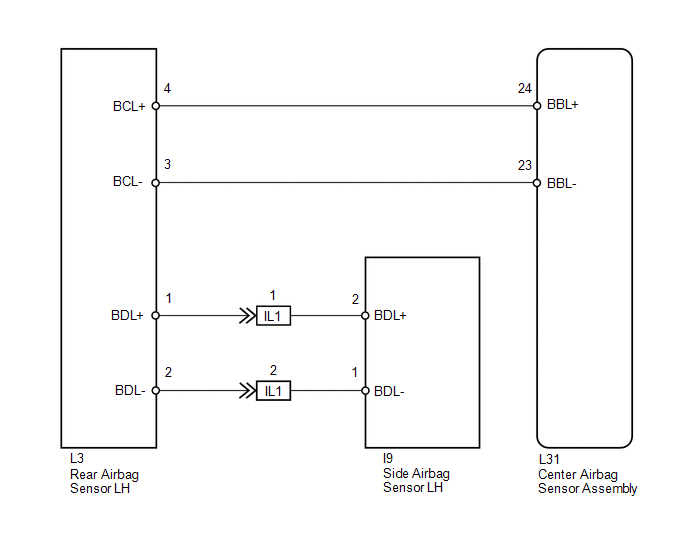
The side collision sensor LH circuit (to determine deployment of the front seat side airbag assembly LH and curtain shield airbag assembly LH) is composed of the center airbag sensor assembly, rear airbag sensor LH and side airbag sensor LH.
The side airbag sensor LH detect impacts to the vehicle and send signals to the center airbag sensor assembly to determine if the airbag should be deployed.
DTC B1695/16 is stored when a malfunction is detected in the side airbag sensor LH.
|
DTC No. |
DTC Detection Condition |
Trouble Area |
|---|---|---|
|
B1695/16 |
|
|
WIRING DIAGRAM
PROCEDURE
|
1. |
CHECK SIDE AIRBAG SENSOR LH |
|
(a) Turn the ignition switch off. |
|
.png)
(b) Disconnect the cable from the negative (-) battery terminal, and wait for at least 90 seconds.
(c) Interchange the side airbag sensor RH with LH and connect the connectors.
(d) Connect the cable to the negative (-) battery terminal.
(e) Turn the ignition switch to ON, and wait for at least 60 seconds.
(f) Clear the DTCs stored in memory (See page
.gif) ).
).
(g) Turn the ignition switch off.
(h) Turn the ignition switch to ON, and wait for at least 60 seconds.
(i) Check for DTCs (See page ).
|
Result |
Proceed to |
|---|---|
|
DTC B1695/16 is output. |
A |
|
DTC B1690/15 is output. |
B |
|
DTCs B1690/15 and B1695/16 are not output. |
C |
|
*1 |
Side Airbag Sensor RH |
|
*2 |
Rear Airbag Sensor LH |
HINT:
Codes other than DTCs B1690/15 and B1695/16 may be output at this time, but they are not related to this check.
| A | .gif) |
REPLACE CENTER AIRBAG SENSOR ASSEMBLY |
| B | |
REPLACE SIDE AIRBAG SENSOR LH |
| C | |
USE SIMULATION METHOD TO CHECK |
 Door Side Airbag Sensor RH Malfunction (B1690/15)
DESCRIPTION
The side collision sensor RH circuit (to determine deployment of the front seat
side airbag assembly RH and curtain shield airbag assembly RH) is composed of the
center airbag sensor ...
 Short in Driver Side Squib Circuit (B1800/51-B1803/51)
DESCRIPTION
The driver side squib circuit consists of the center airbag sensor assembly,
spiral cable and steering pad.
The center airbag sensor assembly uses this circuit to deploy the airbag whe ...
Other materials about Toyota Venza:
Inspection
INSPECTION
PROCEDURE
1. INSPECT FRONT LOWER BALL JOINT
(a) Inspect the turning torque of the ball joint.
(1) Secure the front lower ball joint in a vise using aluminum plates.
(2) Install the nut to the front lower ball joint stud.
(3) U ...
BUS IC Communication Malfunction (B1497/97)
DESCRIPTION
The air conditioning harness connects the A/C amplifier and each servo. The A/C
amplifier supplies power and sends operation instructions to each servo through
the air conditioning harness. Each servo sends the damper position information to
...
Ultrasonic Sensor(for Front Side)
Components
COMPONENTS
ILLUSTRATION
Removal
REMOVAL
PROCEDURE
1. REMOVE FRONT BUMPER ASSEMBLY
(See page )
2. REMOVE NO. 1 ULTRASONIC SENSOR
(a) Disengage the 2 claws to remove the No. 1 ultrasonic sensor.
HINT:
Use the same proc ...

0.1761