Toyota Venza: Components
COMPONENTS
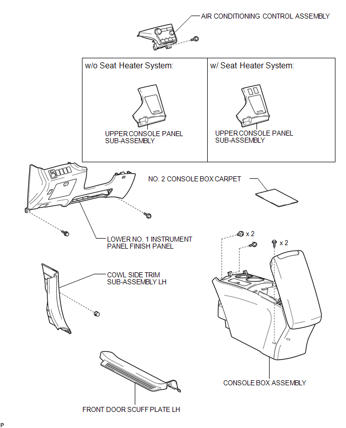
ILLUSTRATION
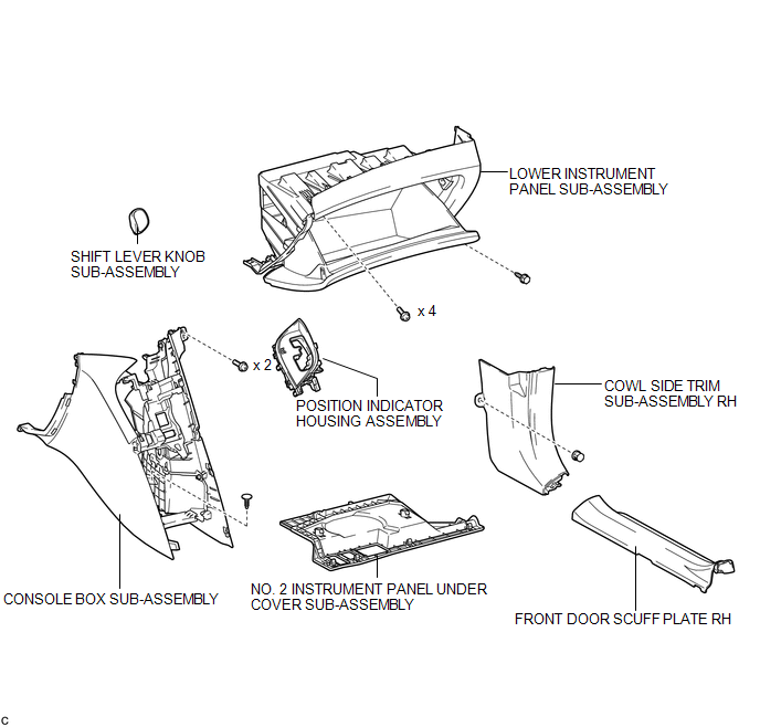
ILLUSTRATION
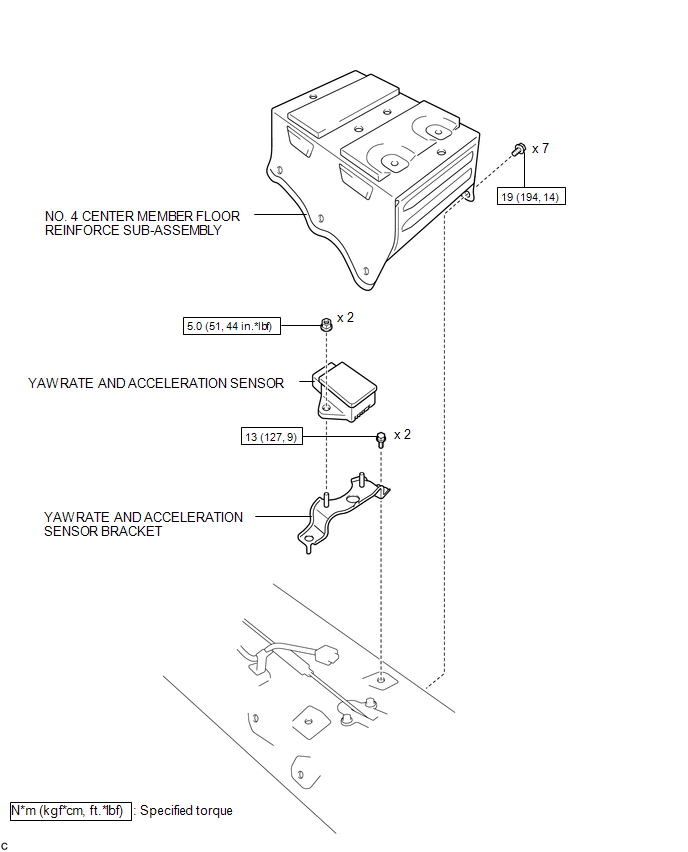
ILLUSTRATION

 Removal
REMOVAL
PROCEDURE
1. DISCONNECT CABLE FROM NEGATIVE BATTERY TERMINAL
CAUTION:
Wait at least 90 seconds after disconnecting the cable from the negative (-)
battery terminal to disable the SRS sys ...
Other materials about Toyota Venza:
Transmitter ID not Registered (C2171/71)
DESCRIPTION
Each tire pressure warning valve and transmitter ID is registered to the tire
pressure warning ECU.
When the ECU detects a transmitter ID code not registered in the ECU, a DTC is
output.
DTC No.
DTC Detection Condition
...
Installation
INSTALLATION
PROCEDURE
1. CLEAN FRONT SIDE FIX WINDOW ASSEMBLY
(a) Clean the outer edges of the front side fix window assembly with
a non-residue solvent.
NOTICE:
Do not touch the glass surface after cleaning it.
Be c ...
No Sound can be Heard from Speakers
PROCEDURE
1.
CHECK AUDIO SETTINGS
(a) In sound output setting mode, set volume, fader and balance to the initial
values and check that the sound is normal.
OK:
Audio system returns to normal.
HINT:
Sound quality adjustm ...

0.1283