Toyota Venza: Security Indicator Light Circuit
DESCRIPTION
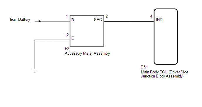
Even when the theft deterrent system is in the disarmed state, the security indicator blinks due to a signal output from the immobiliser system. The security indicator blinks continuously due to a continuous signal received from the immobiliser system while in the armed state.
The main body ECU (driver side junction block assembly) causes the security indicator to come on only during the arming preparation and alarm sounding states.
WIRING DIAGRAM
PROCEDURE
|
1. |
PERFORM ACTIVE TEST USING TECHSTREAM |
(a) Connect the Techstream to the DLC3.
(b) Turn the engine switch on (IG).
(c) Turn the Techstream on.
(d) Select the item below in the Active Test and then check that the indicator operates.
Main Body|
Tester Display |
Test Part |
Control Range |
Diagnostic Note |
|---|---|---|---|
|
Security Indicator |
Security indicator |
ON / OFF |
- |
OK:
The security indicator light flashes and goes off correctly when operated through the Techstream.
| OK | .gif) |
PROCEED TO NEXT SUSPECTED AREA SHOWN IN PROBLEM SYMPTOMS TABLE |
|
.gif)
|
2. |
CHECK HARNESS AND CONNECTOR (ACCESSORY METER ASSEMBLY - MAIN BODY ECU) |
|
(a) Disconnect the D51 main body ECU (driver side junction block assembly) connector. |
|
(b) Disconnect the F2 accessory meter assembly connector.
(c) Measure the resistance according to the value(s) in the table below.
Standard Resistance:
|
Tester Connection |
Condition |
Specified Condition |
|---|---|---|
|
D51-4 (IND) - F2-2 (SEC) |
Always |
Below 1 Ω |
|
D51-4 (IND) - Body ground |
Always |
10 kΩ or higher |
|
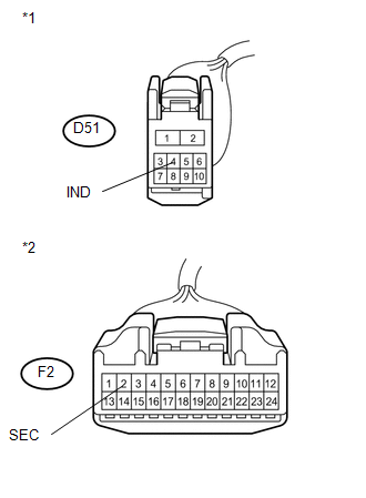
*1 |
Front view of wire harness connector (to Main Body ECU (Driver Side Junction Block Assembly)) |
|
*2 |
Front view of wire harness connector (to Accessory Meter Assembly) |
| NG | |
REPAIR OR REPLACE HARNESS OR CONNECTOR |
|
|
3. |
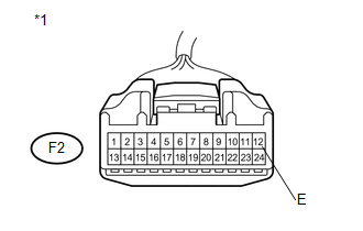
CHECK HARNESS AND CONNECTOR (ACCESSORY METER ASSEMBLY - BODY GROUND) |
|
(a) Measure the resistance according to the value(s) in the table below. Standard Resistance:
|
|
| NG | |
REPAIR OR REPLACE HARNESS OR CONNECTOR |
|
|
4. |
INSPECT ACCESSORY METER ASSEMBLY (SECURITY INDICATOR LIGHT) |
|
(a) Reconnect the F2 accessory meter assembly connector with the D51 ECU connector still disconnected. |
|
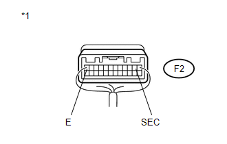
(b) Apply battery voltage from the wire harness back side between the specified terminals of the indicator, and check the lighting condition of the security indicator.
OK :
|
Measurement Condition |
Specified Condition |
|---|---|
|
Battery positive (+) → Terminal F2-2 (SEC) Battery negative (-) → Terminal F2-12 (E) |
Security indicator comes on |
|
*1 |
Component with harness connected (Accessory Meter Assembly) |
NOTICE:
- If the positive (+) lead and the negative (-) lead are incorrectly connected, the security indicator will not come on.
- Voltage of more than 12 V will damage the security indicator.
- If the voltage is too low, the security indicator will not come on.
| OK | |
REPLACE MAIN BODY ECU (DRIVER SIDE JUNCTION BLOCK ASSEMBLY) |
| NG | |
REPLACE ACCESSORY METER ASSEMBLY |
 Security Horn Circuit
DESCRIPTION
When the theft deterrent system is switched from the armed state to the alarm
sounding state, the main body ECU (driver side junction block assembly) controls
the security horn.
WIRI ...
 ECU Power Source Circuit
DESCRIPTION
This circuit provides power for main body ECU (driver side junction block assembly)
operation.
WIRING DIAGRAM
PROCEDURE
1.
CHECK DRIVER SIDE JUNCTION BLOCK A ...
Other materials about Toyota Venza:
ECM Power Source Circuit
DESCRIPTION
When the ignition switch is turned to ON, the battery voltage is applied to IGSW
of the ECM. The output signal from the MREL terminal of the ECM causes a current
to flow to the coil, closing the contact of the engine room junction block assemb ...
Black Screen
PROCEDURE
1.
CHECK DISPLAY SETTING
(a) Check that the display is not in screen off mode.
OK:
The display setting is not in screen off mode.
NG
CHANGE SCREEN TO SCREEN ON MODE
...
Diagnostic Trouble Code Chart
DIAGNOSTIC TROUBLE CODE CHART
Rear View Monitor System
DTC Code
Detection Item
See page
C1622
Back Camera Disconnected
...

0.1246