Toyota Venza: Components
COMPONENTS
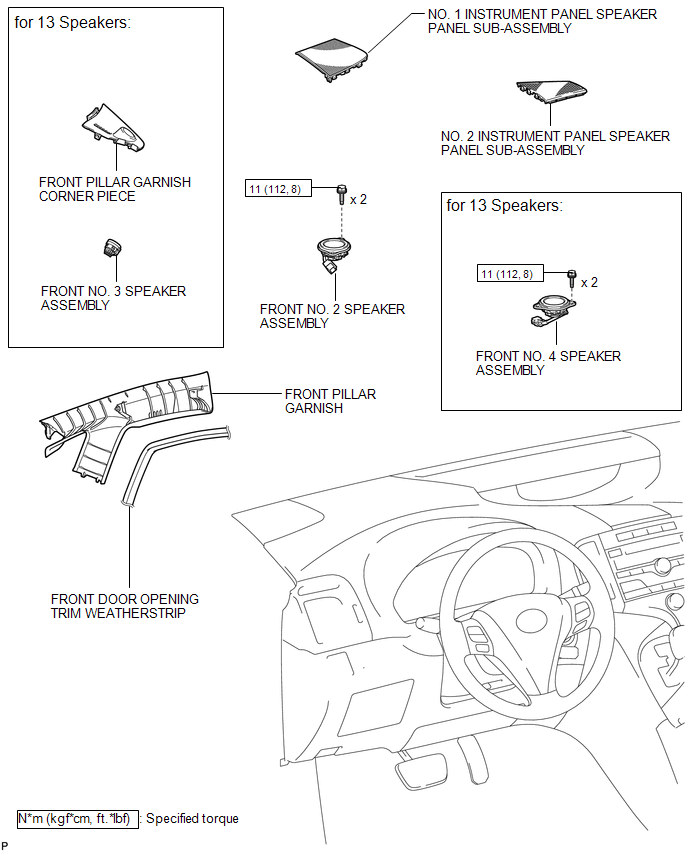
ILLUSTRATION

 Removal
REMOVAL
PROCEDURE
1. DISCONNECT FRONT DOOR OPENING TRIM WEATHERSTRIP
2. REMOVE FRONT PILLAR GARNISH
3. REMOVE NO. 2 INSTRUMENT PANEL SPEAKER PANEL SUB-ASSEMBLY
4. REMOVE FRONT NO. 4 SPEA ...
Other materials about Toyota Venza:
Front Passenger Side Door Entry Unlock Function does not Operate
DESCRIPTION
If the front passenger door entry lock function operates normally, but its entry
unlock function does not, this means that the request code from the front passenger
door is being output normally. In this case, a malfunction in the touch sensor ...
Fuel Injector Circuit
DESCRIPTION
The fuel injector assemblies are located on the intake manifold. They inject
fuel into the cylinders based on signals from the ECM.
WIRING DIAGRAM
CAUTION / NOTICE / HINT
NOTICE:
Inspect the fuses for circuits related to this system befo ...
Main Body Ecu
Components
COMPONENTS
ILLUSTRATION
Removal
REMOVAL
PROCEDURE
1. REMOVE UPPER INSTRUMENT PANEL
HINT:
Refer to the procedure up to Remove Upper Instrument Panel Sub-assembly (See
page ).
2. REMOVE MAIN BODY ECU (DRIVER SIDE JUNCTION BLOCK ASSEM ...

0.1295