Toyota Venza: Inspection
INSPECTION
PROCEDURE
1. INSPECT INTAKE AIR CONTROL VALVE (for ACIS)
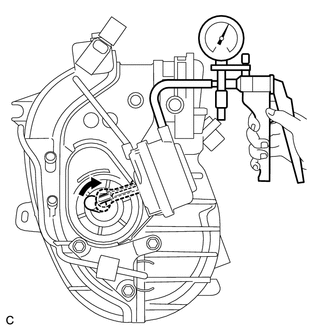
(a) Inspect the diaphragm.
|
(1) Using a vacuum pump, apply a vacuum of 60 kPa (450 mmHg, 17.7 in.Hg) or higher to the diaphragm chamber. Wait for 1 minute and check that the needle of the vacuum pump does not lower. If the result is not as specified, replace the intake manifold. |
|
(b) After applying vacuum in the step above, check that the actuator rod operates.
2. INSPECT VACUUM TANK AND CHECK VALVE
|
(a) Disconnect the vacuum hose from the check valve. |
|
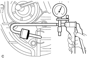
(b) Using a vacuum pump, apply vacuum to the check valve. Wait for 1 minute and check that the needle of the vacuum pump does not lower.
If the result is not as specified, replace the check valve.
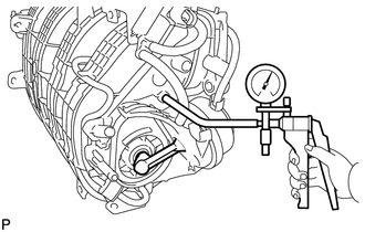
(c) Connect the vacuum hose to the check valve.
|
(d) Using a vacuum pump, apply a vacuum of 60 kPa (450 mmHg, 17.7 in.Hg) or higher to the vacuum tank. Wait for 1 minute and check that the needle of the vacuum pump does not lower. If the result is not as specified, replace the intake manifold. |
|
 Removal
REMOVAL
PROCEDURE
1. DISCHARGE FUEL SYSTEM PRESSURE
HINT:
(See page ).
2. DISCONNECT CABLE FROM NEGATIVE BATTERY TERMINAL
CAUTION:
When disconnecting the cable, some systems need to be initial ...
 Installation
INSTALLATION
PROCEDURE
1. INSTALL ENGINE MOUNTING DAMPER
(a) Install the engine mounting damper with the 3 bolts.
Torque:
9.0 N·m {92 kgf·cm, 80 in·lbf}
...
Other materials about Toyota Venza:
Open in Stop Light Switch Circuit (C1249/49)
DESCRIPTION
The skid control ECU (housed in the actuator assembly) inputs the stop light
switch signal and the condition of brake operation.
The skid control ECU has an open detection circuit, which outputs this DTC when
detecting an open in the stop lig ...
How To Proceed With Troubleshooting
CAUTION / NOTICE / HINT
HINT:
Use the following procedure to troubleshoot the LIN communication system.
*: Use the Techstream.
PROCEDURE
1.
VEHICLE BROUGHT TO WORKSHOP
NEXT
...
Regulations on the use of tire chains
• Regulations regarding the use of tire chains vary according to location and
type of road. Always check local regulations before installing chains.
• Retighten the chains after driving 1/4 - 1/2 mile (0.5 - 1.0 km).
- Tire chains
Observe the fo ...

0.1816