Toyota Venza: Removal
REMOVAL
PROCEDURE
1. DISCONNECT FRONT DOOR OPENING TRIM WEATHERSTRIP
.gif)
2. REMOVE FRONT PILLAR GARNISH
3. REMOVE NO. 2 INSTRUMENT PANEL SPEAKER PANEL SUB-ASSEMBLY
4. REMOVE FRONT NO. 4 SPEAKER ASSEMBLY (for 13 Speakers)
|
(a) Remove the 2 bolts. |
|
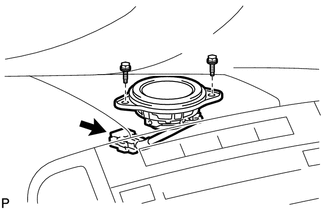
(b) Disconnect the connector and remove the center speaker assembly.
5. REMOVE NO. 1 INSTRUMENT PANEL SPEAKER PANEL SUB-ASSEMBLY
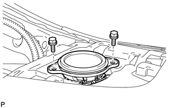
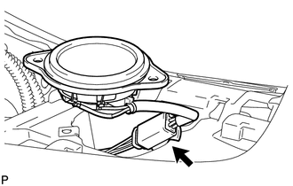
6. REMOVE FRONT NO. 2 SPEAKER ASSEMBLY
|
(a) Remove the 2 bolts. |
|
|
(b) Disconnect the connector and remove the front No. 2 speaker assembly. |
|
7. REMOVE FRONT PILLAR GARNISH CORNER PIECE (for 13 Speakers)
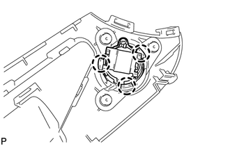
8. REMOVE FRONT NO. 3 SPEAKER ASSEMBLY (for 13 Speakers)
|
(a) Disengage the 3 claws and remove the front No. 3 speaker assembly. |
|
 Components
COMPONENTS
ILLUSTRATION
...
 Inspection
INSPECTION
PROCEDURE
1. INSPECT FRONT NO. 2 SPEAKER ASSEMBLY (for 6 Speakers)
(a) With the speaker installed, check that there is no looseness or other abnormalities.
(b) Check that there is no fo ...
Other materials about Toyota Venza:
Disposal
DISPOSAL
PROCEDURE
1. DISPOSE OF REAR SHOCK ABSORBER
(a) Fully extend the shock absorber piston rod.
(b) Using a drill, make a hole in area B shown in the illustration to discharge
the gas inside. ...
Problem Symptoms Table
PROBLEM SYMPTOMS TABLE
HINT:
Use the table below to help determine the cause of problem symptoms. If multiple
suspected areas are listed, the potential causes of the symptoms are listed in order
of probability in the "Suspected Area" column of ...
Luggage compartment features
- Cargo hooks
Cargo hooks are provided for securing loose items.
- Shopping bag hooks
- Auxiliary box
Lift the right side deck board.
- Luggage cover
Pull out the luggage cover and hook it on the anchors.
Removing luggage ...

0.1215