Toyota Venza: Removal
REMOVAL
PROCEDURE
1. REMOVE REAR WHEELS
2. REMOVE CENTER EXHAUST PIPE ASSEMBLY
(a) Remove the center exhaust pipe assembly.
HINT:
Refer to the instructions for Removal of the exhaust pipe (See page
.gif) for 2GR-FE,
for 2GR-FE,
for 1AR-FE).
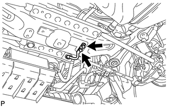
3. REMOVE LOWER NO. 1 EXHAUST PIPE SUPPORT BRACKET
|
(a) Remove the 2 bolts and lower No. 1 exhaust pipe support bracket. |
|
4. SEPARATE REAR STABILIZER LINK ASSEMBLY LH
5. SEPARATE REAR STABILIZER LINK ASSEMBLY RH
6. REMOVE REAR STABILIZER BAR
7. REMOVE REAR HEIGHT CONTROL SENSOR SUB-ASSEMBLY (w/ HID Headlight System)
8. REMOVE REAR NO. 2 SUSPENSION ARM ASSEMBLY LH
9. REMOVE REAR NO. 2 SUSPENSION ARM ASSEMBLY RH
10. REMOVE REAR NO. 1 SUSPENSION ARM ASSEMBLY LH
11. REMOVE REAR NO. 1 SUSPENSION ARM ASSEMBLY RH
12. REMOVE REAR SUSPENSION MEMBER
|
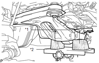
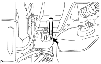
(a) Support the rear suspension member using a jack and 2 wooden blocks as shown in the illustration. Text in Illustration
NOTICE: Make sure to secure the rear suspension member to prevent it from dropping. HINT: Use properly sized wooden blocks to keep the jack and suspension member level. |
|
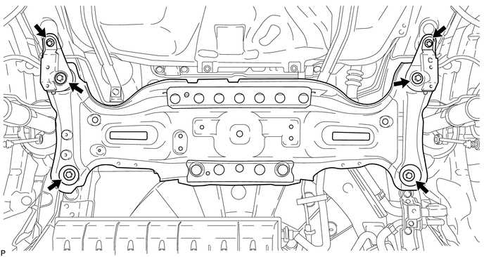
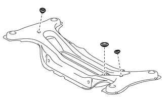
(b) Remove the 4 nuts, 2 bolts and 4 rear lower suspension member stoppers.
(c) Lower the suspension member and rear suspension member.
NOTICE:
When lowering the rear suspension member, be careful not to damage the vehicle body or other components installed on the vehicle.
13. REMOVE REAR SUSPENSION MEMBER BODY MOUNTING FRONT CUSHION LH
|
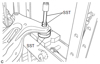
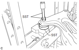
(a) Using SST and a press, remove the rear suspension member body mounting front cushion LH from the rear suspension member sub-assembly. SST: 09527-17011 SST: 09950-60010 09951-00340 SST: 09950-70010 09951-07100 HINT:
|
|
14. REMOVE REAR SUSPENSION MEMBER BODY MOUNTING FRONT CUSHION RH
HINT:
Perform the same procedure as the LH side.
15. REMOVE REAR SUSPENSION MEMBER BODY MOUNTING REAR CUSHION (for LH Side)
|
(a) Using SST and a press, remove the rear suspension member body mounting rear cushion from the rear suspension member sub-assembly. SST: 09527-17011 SST: 09950-60010 09951-00340 SST: 09950-70010 09951-07100 HINT:
|
|
16. REMOVE REAR SUSPENSION MEMBER BODY MOUNTING REAR CUSHION (for RH Side)
HINT:
Perform the same procedure as the LH side.
17. REMOVE HOLE PLUG
|
(a) Remove the 3 hole plugs from the rear suspension member sub-assembly. HINT: There are 2 sizes of the hole plugs. |
|
18. REMOVE STUD BOLT (for LH Side)
|
(a) Remove the stud bolt. |
|
19. REMOVE STUD BOLT (for RH Side)
HINT:
Perform the same procedure as the LH side.
 Components
COMPONENTS
ILLUSTRATION
ILLUSTRATION
ILLUSTRATION
ILLUSTRATION
ILLUSTRATION
...
 Installation
INSTALLATION
PROCEDURE
1. INSTALL STUD BOLT (for LH Side)
(a) Install the stud bolt.
Torque:
17 N·m {173 kgf·cm, 13 ft·lbf}
2. I ...
Other materials about Toyota Venza:
Problem Symptoms Table
PROBLEM SYMPTOMS TABLE
Use the table below to help determine the cause of problem symptoms.
If multiple suspected areas are listed, the potential causes of the symptoms
are listed in order of probability in the "Suspected Area" column ...
Compass
The compass on the inside rear view mirror indicates the direction in which
the vehicle is heading.
- Operation
To turn the compass on or off, push and hold “AUTO” for longer than 3 seconds.
- Displays and directions
Calibrating the c ...
Removal
REMOVAL
PROCEDURE
1. REMOVE REAR WHEELS
2. REMOVE CENTER EXHAUST PIPE ASSEMBLY
(a) Remove the center exhaust pipe assembly.
HINT:
Refer to the instructions for Removal of the exhaust pipe (See page
for 2GR-FE,
for 1AR-FE).
3. REMOVE PROPELLER WITH ...

0.1155