Toyota Venza: Calibration
CALIBRATION
1. SELECT COMPASS DISPLAY MODE
(a) The AUTO switch allows selection of the compass display.
2. PERFORM CALIBRATION
(a) Because each vehicle has its own magnetic field, calibration should be performed. The calibration function is used to compensate for the residual magnetism of the vehicle.
3. WHEN COMPASS IS MAGNETIZED
(a) The compass or vehicle may become magnetized while the vehicle is being shipped. As a result, it is necessary to perform calibration for the compass before the vehicle is delivered to the customer. If calibration cannot be performed successfully (calibration cannot be completed in spite of driving around several times), it may caused by excessive magnetization of the vehicle. Demagnetize the vehicle using a demagnetizer and perform calibration again.
4. SET COMPASS
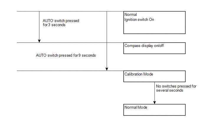
5. CALIBRATION MODE
(a) When the compass is in normal mode, pressing the AUTO switch for 9 seconds will activate the calibration mode.
(b) Drive the vehicle in a circle at a speed of 8 km/h (5 mph) or less.
(c) After driving around in a circle 1 to 3 times, the direction (N, NE, E, SE, S, SW, W or NW) will be displayed on the compass display. This indicates that calibration has finished.
HINT:
After calibration is performed, it is not necessary to repeat the calibration procedure unless magnetic field of the vehicle changes drastically. If the magnetic field changes drastically, the compass display will indicate "C".
 System Diagram
SYSTEM DIAGRAM
...
 Problem Symptoms Table
PROBLEM SYMPTOMS TABLE
Use the table below to help determine the cause of problem symptoms. If multiple
suspected areas are listed, the potential causes of the symptoms are listed in order
of pro ...
Other materials about Toyota Venza:
Back Door Entry Unlock Function does not Operate
DESCRIPTION
If the entry back door open function does not operate but the back door entry
lock function operates, the communication between the vehicle and key is normal.
As a faulty part, the back door open switch circuit (from the back door opener switc ...
Precaution
PRECAUTION
1. PRECAUTION FOR DISCONNECTING THE BATTERY CABLE
NOTICE:
When disconnecting the cable from the negative (-) battery terminal, initialize
the following systems after the cable is reconnected:
System
See Procedure
...
System Description
SYSTEM DESCRIPTION
1. DESCRIPTION OF SYSTEM
(a) Each tire pressure warning valve and transmitter is equipped with a tire
pressure sensor and a transmitter and is installed in each tire and wheel assembly.
The sensor measures the tire pressure. The measur ...

0.1725