Toyota Venza: IG Power Supply Voltage Malfunction (C1551)
DESCRIPTION
The power steering ECU distinguishes the ignition switch status as ON or off through the IG power source circuit.
|
DTC No. |
DTC Detection Condition |
Trouble Area |
|---|---|---|
|
C1551 |
IG power source circuit malfunction inside ECU |
|
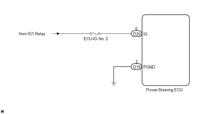
WIRING DIAGRAM
CAUTION / NOTICE / HINT
NOTICE:
- If the power steering ECU has been replaced with a new one, perform
the rotation angle sensor initialization and torque sensor zero point calibration
(See page
.gif) ).
). - Inspection the fuses for circuits related to this system before performing the following inspection procedure.
PROCEDURE
|
1. |
READ VALUE USING TECHSTREAM (IG POWER SUPPLY) |
(a) Turn the ignition switch off.
(b) Connect the Techstream to the DLC3.
(c) Turn the ignition switch to ON.
(d) Turn the Techstream on.
(e) Enter the following menus: Chassis / EMPS / Data List.
(f) Select the items "IG Power Supply" in the Data List and read the value displayed on the Techstream.
EMPS|
Tester Display |
Measurement Item/Range |
Normal Condition |
Diagnostic Note |
|---|---|---|---|
|
IG Power Supply |
ECU power source voltage/ Min.: 0 V Max.: 20.1531 V |
11 to 14 V |
Ignition switch ON |
OK:
Normal condition value is displayed the Techstream.
| OK | .gif) |
REPLACE POWER STEERING ECU |
|
.gif)
|
2. |
CHECK HARNESS AND CONNECTOR (BATTERY - POWER STEERING ECU) |
|
(a) Disconnect the connectors from the power steering ECU. |
|
(b) Measure the voltage according to the value(s) in the table below.
Standard Voltage:
|
Tester Connection |
Switch Condition |
Specified Condition |
|---|---|---|
|
D20-6 (IG) - Body ground |
Ignition switch ON |
11 to 14 V |
(c) Measure the resistance according to the value(s) in the table below.
Standard Resistance:
|
Tester Connection |
Condition |
Specified Condition |
|---|---|---|
|
D19-2 (PGND) - Body ground |
Always |
Below 1 Ω |
|
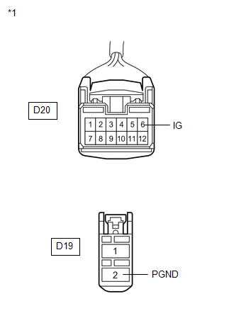
*1 |
Front view of wire harness connector (to Power Steering ECU) |
| OK | |
REPLACE POWER STEERING ECU |
| NG | |
REPAIR OR REPLACE HARNESS OR CONNECTOR |
 Assist Map Number Un-Writing (C1581)
DESCRIPTION
The power steering ECU stores this DTC when it determines that the assist map
is not written in the ECU.
HINT:
The assist map is data written in the power steering ECU to control the ...
 Motor Rotation Angle Sensor Malfunction (C1528)
DESCRIPTION
The motor rotation angle sensor detects the motor rotation angle and sends this
information to the power steering ECU.
DTC No.
DTC Detection Condition
...
Other materials about Toyota Venza:
ECU Power Source Circuit
DESCRIPTION
This circuit provides power to operate the transponder key ECU assembly.
WIRING DIAGRAM
CAUTION / NOTICE / HINT
NOTICE:
If the transponder key ECU assembly is replaced, register the key and ECU communication
ID (See page ).
PROCEDURE
...
On-vehicle Inspection
ON-VEHICLE INSPECTION
PROCEDURE
1. CHECK POWER SOURCE MODE CHANGE FUNCTION
(a) Check the function of the engine switch.
(1) Check that power source mode changes in accordance with the conditions of
the shift position and brake pedal.
Brake Pe ...
Terminals Of Ecu
TERMINALS OF ECU
1. CHECK MAIN BODY ECU (DRIVER SIDE JUNCTION BLOCK ASSEMBLY)
(a) Disconnect the 2C, 2F and 2K main body ECU (driver side junction block assembly)
connectors.
(b) Measure the voltage and resistance according to the value(s) in the table ...

0.1451