Toyota Venza: System Diagram
SYSTEM DIAGRAM
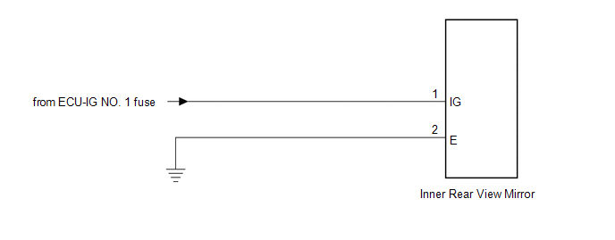
 Components
COMPONENTS
ILLUSTRATION
...
 Calibration
CALIBRATION
1. SELECT COMPASS DISPLAY MODE
(a) The AUTO switch allows selection of the compass display.
2. PERFORM CALIBRATION
(a) Because each vehicle has its own magnetic field, calibration shou ...
Other materials about Toyota Venza:
Brake fluid
- Checking fluid level
The brake fluid level should be between the “MAX” and “MIN” lines on the tank.
Make sure to check the fluid type and prepare the necessary items.
- Adding fluid
- Brake fluid can absorb moisture from the ...
System Diagram
SYSTEM DIAGRAM
Communication Method
Transmitting ECU
Receiver
Signal
Communication Method
Main body ECU (Driver Side Junction Block Assembly)
Power back door ECU (Power back door motor ...
Installation
INSTALLATION
PROCEDURE
1. INSTALL REAR SEAT INNER BELT ASSEMBLY RH
(a) Install the rear seat inner belt assembly RH with the bolt.
Torque:
42 N·m {428 kgf·cm, 31 ft·lbf}
2. INSTALL REAR SE ...

0.1417