Toyota Venza: Back-up Power Source Circuit
DESCRIPTION
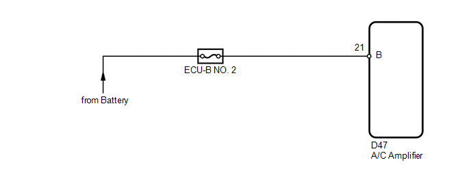
The back-up power source circuit for the A/C amplifier is shown below. Power is supplied even when the ignition switch is turned off. The power is used for diagnostic trouble code memory, etc.
WIRING DIAGRAM
CAUTION / NOTICE / HINT
NOTICE:
Inspect the fuses for circuits related to this system before performing the following inspection procedure.
PROCEDURE
|
1. |
CHECK HARNESS AND CONNECTOR (A/C AMPLIFIER - BATTERY) |
|
(a) Disconnect the A/C amplifier connector. |
|
(b) Measure the voltage according to the value(s) in the table below.
Standard Voltage:
|
Tester Connection |
Condition |
Specified Condition |
|---|---|---|
|
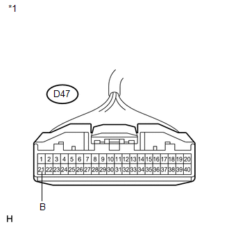
D47-21 (B) - Body ground |
Always |
11 to 14 V |
|
*1 |
Front view of wire harness connector (to A/C Amplifier) |
| OK | .gif) |
PROCEED TO NEXT SUSPECTED AREA SHOWN IN PROBLEM SYMPTOMS TABLE |
| NG | |
REPAIR OR REPLACE HARNESS OR CONNECTOR |
 IG Power Source Circuit
DESCRIPTION
The main power source is supplied to the A/C amplifier when the ignition switch
is ON.
The power source is used for operating the A/C amplifier and servo motor, etc.
WIRING DIAGRAM
...

Other materials about Toyota Venza:
Reassembly
REASSEMBLY
CAUTION / NOTICE / HINT
NOTICE:
Before installation, apply high temperature grease to the parts indicated by
arrows (See page ).
PROCEDURE
1. INSTALL NO. 2 PARKING BRAKE SHOE HOLD DOWN SPRING PIN (for 2WD)
(a) Install the No. 2 p ...
Inspection
INSPECTION
PROCEDURE
1. INSPECT ENGINE SWITCH
(a) Measure the resistance according to the value(s) in the table below.
Standard Resistance:
Tester Connection
Switch Condition
Specified Condition
7 (SS1) ...
Removal
REMOVAL
PROCEDURE
1. REMOVE POWER DISTRIBUTION
(a) Remove the bolt.
(b) Disengage the 2 claws and disconnect the power distribution from the relay
box as shown in the illustration.
(c) ...

0.1468