Toyota Venza: AWD Warning Light Remains ON
DESCRIPTION
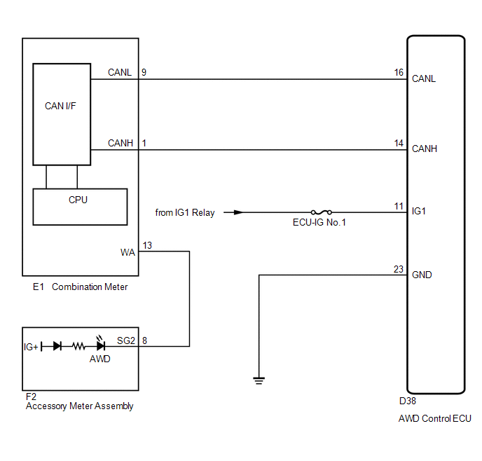
The AWD control ECU is connected to the combination meter via the CAN communication system.
If the AWD control ECU stores any DTCs which are related to the active torque control 4WD system, the AWD warning light comes on in the combination meter.
WIRING DIAGRAM
CAUTION / NOTICE / HINT
HINT:
Check the condition of each related circuit connector before troubleshooting
(See page .gif) ).
).
PROCEDURE
|
1. |
CHECK FOR DTC |
(a) Check if the CAN communication system DTC is output (See page
).
(b) Check if the active torque control 4WD system DTC is output (See page
).
|
Result |
Proceed to |
|---|---|
|
Neither CAN communication system DTC nor active torque control 4WD system DTC is output |
A |
|
CAN communication DTC is output |
B |
|
Active torque control 4WD system DTC is output |
C |
HINT:
When DTCs indicating a CAN communication system malfunction are output, repair the CAN communication system before repairing each corresponding sensor.
| B | .gif) |
REPAIR CIRCUIT INDICATOR BY OUTPUT CODE (CAN COMMUNICATION SYSTEM) |
| C | |
REPAIR CIRCUIT INDICATOR BY OUTPUT CODE (ACTIVE TORQUE CONTROL 4WD SYSTEM) |
|
.gif)
|
2. |
CHECK IF AWD CONTROL ECU CONNECTOR IS SECURELY CONNECTED |
(a) Check if the skid control ECU connector is securely connected.
OK:
The connector is securely connected.
| NG | |
CONNECT CONNECTOR TO ECU CORRECTLY |
|
|
3. |
CHECK BATTERY |
(a) Check the battery voltage.
Standard voltage:
11 to 14 V
|
Result |
Proceed to |
|---|---|
|
OK |
A |
|
NG (2GR-FE) |
B |
|
NG (1AR-FE) |
C |
| B | |
INSPECT CHARGING SYSTEM (2GR-FE) |
| C | |
INSPECT CHARGING SYSTEM (1AR-FE) |
|
|
4. |
PERFORM ACTIVE TEST (AWD WARNING LIGHT) |
(a) Warm up the engine.
(b) Turn the ignition switch off.
(c) Connect the Techstream to the DLC3.
(d) Turn the ignition switch to ON.
(e) Turn the Techstream on.
(f) Enter the following menus: Chassis / 4WD / Active Test.
(g) According to the display on the Techstream, perform the Active Test.
Chassis / 4WD / Active Test|
Tester Display |
Test Part |
Control Range |
Diagnostic Note |
|---|---|---|---|
|
4WD Warning Light |
AWD warning light |
Warning light is ON/OFF |
Observer combination meter |
OK:
The AWD warning light turns off.
| OK | |
REPLACE AWD CONTROL ECU |
|
|
5. |
CHECK WIRE HARNESS OR CONNECTOR (AWD CONTROL ECU - BATTERY) |
|
(a) Disconnect the ECU connector. |
|
.png)
(b) Turn the ignition switch to ON.
(c) Measure the voltage of the wire harness side connector.
Standard Voltage:
|
Tester Connection |
Condition |
Specified Condition |
|---|---|---|
|
D38-11 (IG1) - Body Ground |
Ignition switch ON |
11 to 14 V |
|
*1 |
Rear view of wire harness connector (to AWD Control ECU) |
| NG | |
REPAIR OR REPLACE HARNESS OR CONNECTOR |
|
|
6. |
CHECK WIRE HARNESS OR CONNECTOR (AWD CONTROL ECU - BODY GROUND) |
|
(a) Disconnect the ECU connector. |
|
.png)
(b) Measure the resistance of the wire harness side connector.
Standard Resistance:
|
Tester Connection |
Condition |
Specified Condition |
|---|---|---|
|
D38-23 (GND) - Body Ground |
Always |
Below 1 Ω |
|
*1 |
Rear view of wire harness connector (to AWD Control ECU) |
| OK | |
GO TO METER / GAUGE SYSTEM |
| NG | |
REPAIR OR REPLACE HARNESS OR CONNECTOR |
 AWD Warning Light does not Come ON
DESCRIPTION
Refer to "AWD Warning Light Remains ON" (See page
).
WIRING DIAGRAM
Refer to "AWD Warning Light Remains ON" (See page
).
CAUTION / NOTICE / HINT
Check the cond ...
 TC and CG Terminal Circuit
DESCRIPTION
Connecting terminals TC and CG of the DLC3 causes the AWD control ECU to display
2-digit DTCs by flashing the AWD warning light.
HINT:
When each warning light remains blinking, a shor ...
Other materials about Toyota Venza:
Main Body ECU Vehicle Information Reading/Writing Process Malfunction (B15F6)
DESCRIPTION
This DTC is stored when items controlled by the main body ECU (multiplex network
body ECU) cannot be customized via the navigation system vehicle customization screen.
HINT:
The main body ECU (multiplex network body ECU) controls the items ...
Definition Of Terms
DEFINITION OF TERMS
Term
Definition
Monitor description
Description of what the TCM monitors and how it detects malfunctions
(monitoring purpose and its details).
Related DTCs
D ...
Sending Malfunction (Navigation to APGS) (U0073,U0100,U0140,U0155)
DESCRIPTION
These DTCs are stored when a malfunction occurs in the CAN communication circuit.
DTC No.
DTC Detection Condition
Trouble Area
U0073
CAN bus connection error
CAN communicatio ...

0.154