Toyota Venza: Terminals Of Ecu
TERMINALS OF ECU
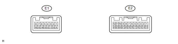
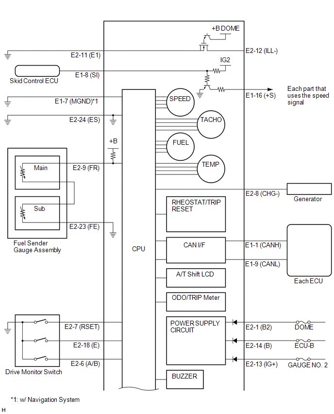
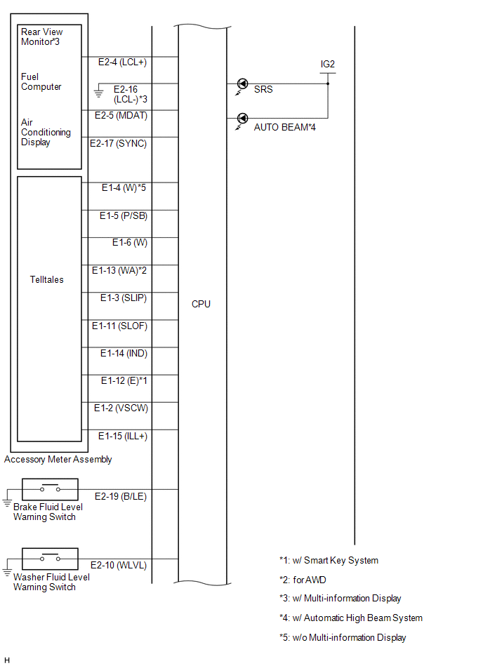
1. COMBINATION METER ASSEMBLY
(a) Measure the voltage and resistance according to the value(s) in the table below.
|
Terminal No. (Symbol) |
Wiring Color |
Terminal Description |
Condition |
Specified Condition |
|---|---|---|---|---|
|
E1-1 (CANH) - Body ground |
LG - Body ground |
CAN communication signal |
Ignition switch off |
200 Ω or higher |
|
E1-2 (VSCW) - Body ground |
V - Body ground |
TRAC OFF indicator light signal |
Ignition switch ON, TRAC OFF indicator light off |
11 to 14 V |
|
Ignition switch ON, TRAC OFF indicator light blinks |
Below 1 V |
|||
|
E1-3 (SLIP) - Body ground |
R - Body ground |
Slip indicator light signal |
Ignition switch ON, slip indicator light off |
11 to 14 V |
|
Ignition switch ON, slip indicator light blinks |
Below 1 V |
|||
|
E1-4 (W)*4 - Body ground |
GR - Body ground |
Washer level warning light signal |
Ignition switch ON, washer level warning light off |
11 to 14 V |
|
Ignition switch ON, washer level warning light on |
Below 1 V |
|||
|
E1-5 (P/SB) - Body ground |
G - Body ground |
Front passenger side seat belt warning light signal |
Ignition switch ON, front passenger side seat belt warning light off |
11 to 14 V |
|
Ignition switch ON, front passenger side seat belt warning light on |
Below 1 V |
|||
|
E1-6 (W) - Body ground |
P - Body ground |
Tire pressure warning light signal |
Ignition switch ON, tire pressure warning light off |
11 to 14 V |
|
Ignition switch ON, tire pressure warning light on |
Below 1 V |
|||
|
E1-7 (MGND)*1 - Body ground |
B - Body ground |
Ground |
Always |
Below 1 V |
|
E1-8 (SI) - Body ground |
V - Body ground |
Speed signal (Input) |
Ignition switch ON, front wheel turns slowly |
Pulse generation (See waveform 1) |
|
E1-9 (CANL) - Body ground |
W - Body ground |
CAN communication signal |
Ignition switch off |
200 Ω or higher |
|
E1-11 (SLOF) - Body ground |
P - Body ground |
VSC OFF indicator light signal |
Ignition switch ON, VSC OFF indicator light off |
11 to 14 V |
|
Ignition switch ON, VSC OFF indicator light on |
Below 1 V |
|||
|
E1-12 (E)*6 - Body ground |
LG - Body ground |
Key warning light*4 or master warning light*3 signal |
Ignition switch ON, key warning light*4 or master warning light*3 off |
11 to 14 V |
|
Ignition switch ON, key warning light*4 or master warning light*3 on |
Below 1 V |
|||
|
E1-13 (WA)*5 - Body ground |
L - Body ground |
AWD warning light signal |
Ignition switch ON, AWD warning light off |
11 to 14 V |
|
Ignition switch ON, AWD warning light on |
Below 1 V |
|||
|
E1-14 (IND) - Body ground |
V - Body ground |
EPS warning light signal |
Ignition switch ON, EPS warning light off |
11 to 14 V |
|
Ignition switch ON, EPS warning light on |
Below 1 V |
|||
|
E1-15 (ILL+) - Body ground |
SB - Body ground |
Illumination signal |
Headlight dimmer switch off |
Below 1 V |
|
Headlight dimmer switch tail or head |
11 to 14 V |
|||
|
E1-16 (+S) - Body ground |
L - Body ground |
Speed signal for other systems (Output) |
Ignition switch ON, front wheel turns slowly |
Pulse generation (See waveform 1) |
|
E2-1 (B2) - Body ground |
L - Body ground |
Battery |
Always |
11 to 14 V |
|
E2-2 (B) - Body ground |
P - Body ground |
Turn indicator light signal |
Ignition switch ON, turn RH indicator light off |
11 to 14 V |
|
Ignition switch ON, turn RH indicator light blinks |
Below 1 V |
|||
|
E2-3 (B) - Body ground |
SB - Body ground |
Turn indicator light signal |
Ignition switch ON, turn LH indicator light off |
11 to 14 V |
|
Ignition switch ON, turn LH indicator light blinks |
Below 1 V |
|||
|
E2-4 (LCL+) - Body ground |
LG - Body ground |
Accessory meter assembly communication signal |
Always |
Pulse generation |
|
E2-5 (MDAT) - Body ground |
P - Body ground |
Accessory meter assembly communication signal |
Always |
Pulse generation |
|
E2-6 (A/B) - Body ground |
L - Body ground |
Drive monitor switch signal (INFO CLOCK*4 or INFO*3 switch) |
Ignition switch ON, INFO CLOCK*4 or INFO*3 switch pressed |
Below 1 V |
|
Ignition switch ON, INFO CLOCK*4 or INFO*3 switch not pressed |
11 to 14 V |
|||
|
E2-7 (RSET) - Body ground |
SB - Body ground |
Drive monitor switch signal (RESET H*4 or SELECT RESET*3 switch) |
Ignition switch ON, RESET H*4 or SELECT RESET*3 switch pressed |
Below 1 V |
|
Ignition switch ON, RESET H*4 or SELECT RESET*3 switch not pressed |
11 to 14 V |
|||
|
E2-8 (CHG-) - Body ground |
Y - Body ground |
Charge warning light signal |
Ignition switch ON, charge warning light off |
11 to 14 V |
|
Ignition switch ON, oil pressure warning light on |
Below 1 V |
|||
|
E2-9 (FR) - Body ground |
V - Body ground |
Fuel level signal |
Ignition switch ON, fuel level warning light off |
Below 1 V |
|
Ignition switch ON, fuel level warning light on |
3 to 7 V |
|||
|
E2-10 (WLVL) - Body ground |
L - Body ground |
Washer level warning light signal |
Ignition switch ON, washer level warning light off |
11 to 14 V |
|
Ignition switch ON, washer level warning light blinks |
Below 1 V |
|||
|
E2-11 (E1) - Body ground |
B - Body ground |
Ground (Power ground) |
Always |
Below 1 V |
|
E2-12 (ILL-) - Body ground |
L - Body ground |
Illumination signal |
Headlight dimmer switch off |
Below 1 V |
|
Headlight dimmer switch tail or head |
11 to 14 V |
|||
|
E2-13 (IG+) - Body ground |
BR - Body ground |
Ignition switch signal |
Ignition switch ON |
11 to 14 V |
|
E2-14 (B) - Body ground |
Y - Body ground |
Battery |
Always |
11 to 14 V |
|
E2-16 (LCL-)*3 - Body ground |
B - Body ground |
Ground |
Always |
Below 1 V |
|
E2-17 (SYNC) - Body ground |
R - Body ground |
Accessory meter assembly communication signal |
Always |
Pulse generation |
|
E2-18 (E) - Body ground |
G - Body ground |
Drive monitor switch signal (US/M M*4 or SETUP*3 switch) |
Ignition switch ON, US/M M*4 or SETUP*3 switch pressed |
Below 1 V |
|
Ignition switch ON, US/M M*4 or SETUP*3 switch not pressed |
11 to 14 V |
|||
|
E2-19 (B/LE) - Body ground |
BE - Body ground |
Brake fluid level warning light signal |
Ignition switch ON, brake fluid level warning light off |
Below 1 V |
|
Ignition switch ON, brake fluid level warning light on |
11 to 14 V |
|||
|
E2-20 (S) - Body ground |
P - Body ground |
Oil pressure switch signal |
Ignition switch ON, oil pressure warning light off |
Below 1 V |
|
Ignition switch ON, oil pressure warning light on |
11 to 14 V |
|||
|
E2-21 (TIRE) - Body ground |
LG - Body ground |
Tire pressure warning light signal |
Ignition switch ON, tire pressure warning light off |
11 to 14 V |
|
Ignition switch ON, tire pressure warning light blinks |
Below 1 V |
|||
|
E2-22 (LVWG)*7 - Body ground |
BR - Body ground |
Leveling indicator light signal |
Ignition switch ON, leveling indicator light off |
11 to 14 V |
|
Ignition switch ON, leveling indicator light blinks |
Below 1 V |
|||
|
E2-23 (FE) - Body ground |
R - Body ground |
Ground (Fuel ground) |
Always |
Below 1 V |
|
E2-24 (ES) - Body ground |
W - Body ground |
Ground (Signal ground) |
Always |
Below 1 V |
- *1: w/ Navigation System
- *2: w/o Smart Key System
- *3: w/ Multi-information Display
- *4: w/o Multi-information Display
- *5: for AWD
- *6: w/ Smart Key System
- *7: w/ Automatic Type Headlight Beam Level Control
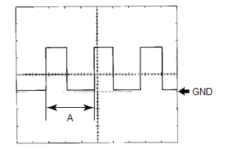
(b) Waveform 1 (Reference): Using an oscilloscope:
|
Item |
Condition |
|---|---|
|
Tool setting |
5 V/DIV., 20 ms./DIV. |
|
Vehicle condition |
Ignition switch ON, front wheel turns slowly |
HINT:
When the system is functioning normally, one wheel revolution generates 4 pulses. As the vehicle speed increases, the width indicated by (A) in the illustration narrows.
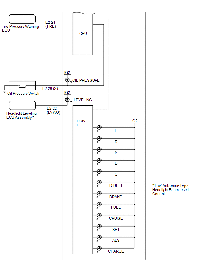
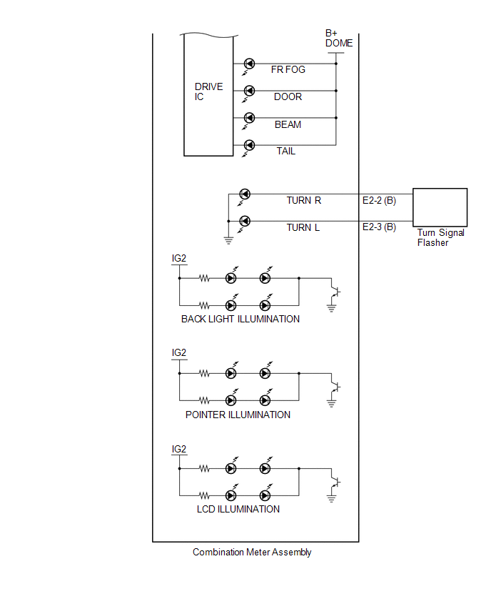
2. COMBINATION METER ASSEMBLY INNER CIRCUIT
(a) Combination Meter Assembly Inner Circuit
|
Terminal No. (Symbol) |
Wire Harness Side |
|
|---|---|---|
|
E1 |
1 (CANH) |
CAN Communication Line |
|
2 (VSCW) |
Accessory Meter Assembly |
|
|
3 (SLIP) |
Accessory Meter Assembly |
|
|
4 (W) |
Accessory Meter Assembly*4 |
|
|
5 (P/SB) |
Accessory Meter Assembly |
|
|
6 (W) |
Accessory Meter Assembly |
|
|
7 (MGND) |
Ground*1 |
|
|
8 (SI) |
Skid Control ECU |
|
|
9 (CANL) |
CAN Communication Line |
|
|
10 |
- |
|
|
11 (SLOF) |
Accessory Meter Assembly |
|
|
12 (E) |
Accessory Meter Assembly*5 |
|
|
13 (WA) |
Accessory Meter Assembly*2 |
|
|
14 (IND) |
Accessory Meter Assembly |
|
|
15 (ILL+) |
Accessory Meter Assembly |
|
|
16 (+S) |
Each part that uses the speed signal |
|
|
E2 |
1 (B2) |
DOME Fuse |
|
2 (B) |
Turn Signal Flasher |
|
|
3 (B) |
Turn Signal Flasher |
|
|
4 (LCL+) |
Accessory Meter Assembly |
|
|
5 (MDAT) |
Accessory Meter Assembly |
|
|
6 (A/B) |
Drive Monitor Switch (INFO CLOCK*4 or INFO*3 Switch) |
|
|
7 (RSET) |
Drive Monitor Switch (RESET H*4 or SELECT RESET*3 Switch) |
|
|
8 (CHG-) |
Generator |
|
|
9 (FR) |
Fuel Sender Gauge Assembly |
|
|
10 (WLVL) |
Washer Level Warning Switch |
|
|
11 (E1) |
Ground |
|
|
12 (ILL-) |
Each illumination part |
|
|
13 (IG+) |
GAUGE NO. 2 Fuse |
|
|
14 (B) |
ECU-B Fuse |
|
|
15 |
- |
|
|
16 (LCL-) |
Ground*3 |
|
|
17 (SYNC) |
Accessory Meter Assembly |
|
|
18 (E) |
Drive Monitor Switch (US/M M*4 or SETUP*3 Switch) |
|
|
19 (B/LE) |
Brake Fluid Level Warning Switch |
|
|
20 (S) |
Oil Pressure Switch |
|
|
21 (TIRE) |
Tire Pressure Warning ECU |
|
|
22 (LVWG) |
Headlight Leveling ECU Assembly*6 |
|
|
23 (FE) |
Ground (Fuel Sender Gauge Assembly Ground) |
|
|
24 (ES) |
Ground (Signal Ground) |
|
- *1: w/ Navigation System
- *2: for AWD
- *3: w/ Multi-information Display
- *4: w/o Multi-information Display
- *5: w/ Smart Key System
- *6: w/ Automatic Type Headlight Beam Level Control
3. ACCESSORY METER ASSEMBLY
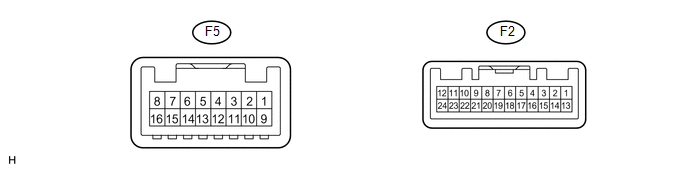
(a) Measure the voltage and resistance according to the value(s) in the table below.
|
Terminal No. (Symbol) |
Wiring Color |
Terminal Description |
Condition |
Specified Condition |
|---|---|---|---|---|
|
F5-1 (IG)*1 - Body ground |
P - Body ground |
Ignition switch signal |
Ignition switch off |
Below 1 V |
|
Ignition switch ON |
11 to 14 V |
|||
|
F5-2 (HSI+)*1 - Body ground |
LG - Body ground |
Communication signal |
Ignition switch off |
Below 1 V |
|
F5-6 (SYNC)*1 - Body ground |
R - Body ground |
Communication signal |
Always |
Pulse generation |
|
F5-9 (+B)*1 - Body ground |
L - Body ground |
Battery |
Always |
11 to 14 V |
|
F5-12 (DATA)*1 - Body ground |
P - Body ground |
Communication signal |
Always |
Pulse generation |
|
F5-16 (SGND)*1 - Body ground |
B - Body ground |
Ground |
Always |
Below 1 V |
|
F2-1 (B) - Body ground |
P - Body ground |
Battery |
Always |
11 to 14 V |
|
F2-2 (SEC)*4 - Body ground |
SB - Body ground |
Security indicator light signal |
Ignition switch ON, security indicator light off |
11 to 14 V |
|
Ignition switch ON, security indicator light blinks |
Below 1 Ω |
|||
|
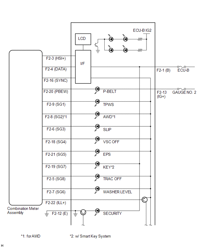
F2-3 (HSI+)*5 - Body ground |
LG - Body ground |
Communication signal |
Ignition switch off |
Below 1 V |
|
F2-4 (DATA)*5 - Body ground |
P - Body ground |
Communication signal |
Always |
Pulse generation |
|
F2-5 (SG8) - Body ground |
V - Body ground |
TRAC OFF indicator light signal |
Ignition switch ON, TRAC OFF indicator light off |
11 to 14 V |
|
Ignition switch ON, TRAC OFF indicator light blinks |
Below 1 V |
|||
|
F2-6 (SG3) - Body ground |
R - Body ground |
Slip indicator light signal |
Ignition switch ON, slip indicator light off |
11 to 14 V |
|
Ignition switch ON, slip indicator light blinks |
Below 1 V |
|||
|
F2-7 (SG6)*5 - Body ground |
GR - Body ground |
Washer level warning light signal |
Ignition switch ON, washer level warning light off |
11 to 14 V |
|
Ignition switch ON, washer level warning light on |
Below 1 V |
|||
|
F2-8 (SG2)*2 - Body ground |
L - Body ground |
AWD warning light signal |
Ignition switch ON, AWD warning light off |
11 to 14 V |
|
Ignition switch ON, AWD warning light on |
Below 1 V |
|||
|
F2-9 (SG1) - Body ground |
P - Body ground |
Tire pressure warning light signal |
Ignition switch ON, tire pressure warning light off |
11 to 14 V |
|
Ignition switch ON, tire pressure warning light on |
Below 1 V |
|||
|
F2-10 (CHK) - Body ground |
R - Body ground |
MIL (Check engine warning light) signal |
Ignition switch ON, tire pressure warning light off |
11 to 14 V |
|
Ignition switch ON, tire pressure warning light on |
Below 1 V |
|||
|
F2-11 (P-AB) - Body ground |
GR - Body ground |
Passenger airbag OFF indicator light signal |
Ignition switch ON, passenger airbag OFF indicator light off |
11 to 14 V |
|
Ignition switch ON, passenger airbag OFF indicator light on |
Below 1 V |
|||
|
F2-12 (E) - Body ground |
B - Body ground |
Ground |
Always |
Below 1 Ω |
|
F2-13 (IG+) - Body ground |
L - Body ground |
Ignition switch signal |
Ignition switch off |
Below 1 V |
|
Ignition switch ON |
11 to 14 V |
|||
|
F2-14 (LP) - Body ground |
Y - Body ground |
Security indicator light signal |
Ignition switch ON, security indicator light off |
11 to 14 V |
|
Ignition switch ON, security indicator light blinks |
11 to 14 V ←→ Below 1 V |
|||
|
F2-16 (SYNC)*5 - Body ground |
R - Body ground |
Communication signal |
Always |
Pulse generation |
|
F2-18 (SG4) - Body ground |
P - Body ground |
VSC OFF indicator light signal |
Ignition switch ON, VSC OFF indicator light off |
11 to 14 V |
|
Ignition switch ON, VSC OFF indicator light on |
Below 1 V |
|||
|
F2-19 (SG7)*3 - Body ground |
LG - Body ground |
Key warning light*5 or master warning light*1 signal |
Ignition switch ON, key warning light*5 or master warning light*1 off |
11 to 14 V |
|
Ignition switch ON, key warning light*5 or master warning light*1 on |
Below 1 V |
|||
|
F2-20 (PBEW) - Body ground |
G - Body ground |
Front passenger side seat belt warning light signal |
Ignition switch ON, front passenger side seat belt warning light off |
11 to 14 V |
|
Ignition switch ON, front passenger side seat belt warning light on |
Below 1 V |
|||
|
F2-21 (SG5) - Body ground |
V - Body ground |
EPS warning light signal |
Ignition switch ON, EPS warning light off |
11 to 14 V |
|
Ignition switch ON, EPS warning light on |
Below 1 V |
|||
|
F2-22 (ILL+) - Body ground |
SB - Body ground |
Illumination signal |
Headlight dimmer switch off |
Below 1 V |
|
Headlight dimmer switch tail or head |
11 to 14 V |
|||
|
F2-23 (PAON) - Body ground |
Y - Body ground |
Passenger airbag ON indicator light signal |
Ignition switch ON, passenger airbag ON indicator light off |
11 to 14 V |
|
Ignition switch ON, passenger airbag ON indicator light on |
Below 1 V |
- *1: w/ Multi-information Display
- *2: for AWD
- *3: w/ Smart Key System
- *4: w/ Theft Deterrent System
- *5: w/o Multi-information Display
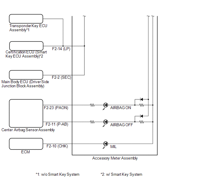
4. ACCESSORY METER ASSEMBLY INNER CIRCUIT
(a) w/o Multi-information Display
|
Terminal No. (Symbol) |
Wire Harness Side |
|
|---|---|---|
|
F2 |
1 (B) |
ECU-B Fuse |
|
2 (SEC) |
Main Body ECU (Driver Side Junction Block Assembly) |
|
|
3 (HSI+) |
Combination Meter Assembly |
|
|
4 (DATA) |
Combination Meter Assembly |
|
|
5 (SG8) |
Combination Meter Assembly |
|
|
6 (SG3) |
Combination Meter Assembly |
|
|
7 (SG6) |
Combination Meter Assembly |
|
|
8 (SG2) |
Combination Meter Assembly*1 |
|
|
9 (SG1) |
Combination Meter Assembly |
|
|
10 (CHK) |
ECM |
|
|
11 (P-AB) |
Center Airbag Sensor Assembly |
|
|
12 (E) |
Ground |
|
|
13 (IG+) |
GAUGE NO. 2 Fuse |
|
|
14 (LP) |
Certification ECU (Smart Key ECU Assembly)*2 or Transponder Key ECU Assembly*3 |
|
|
15 |
- |
|
|
16 (SYNC) |
Combination Meter Assembly |
|
|
17 |
- |
|
|
18 (SG4) |
Combination Meter Assembly |
|
|
19 (SG7) |
Combination Meter Assembly*2 |
|
|
20 (PBEW) |
Combination Meter Assembly |
|
|
21 (SG5) |
Combination Meter Assembly |
|
|
22 (ILL+) |
Combination Meter Assembly |
|
|
23 (PAON) |
Center Airbag Sensor Assembly |
|
|
24 |
- |
|
- *1: for AWD
- *2: w/ Smart Key System
- *3: w/o Smart Key System
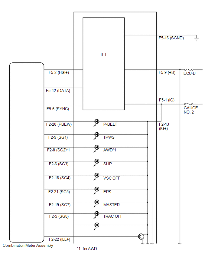
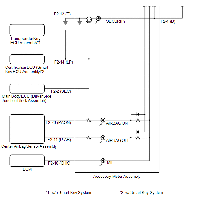
(b) w/ Multi-information Display
|
Terminal No. (Symbol) |
Wire Harness Side |
|
|---|---|---|
|
F5 |
1 (IG) |
GAUGE NO. 2 Fuse |
|
2 (HSI+) |
Combination Meter Assembly |
|
|
3 |
- |
|
|
4 |
- |
|
|
5 |
- |
|
|
6 (SYNC) |
Combination Meter Assembly |
|
|
7 |
- |
|
|
8 |
- |
|
|
9 (+B) |
ECU-B Fuse |
|
|
10 |
- |
|
|
11 |
- |
|
|
12 (DATA) |
Combination Meter Assembly |
|
|
13 |
- |
|
|
14 |
- |
|
|
15 |
- |
|
|
16 (SGND) |
Ground |
|
|
F2 |
1 (B) |
ECU-B Fuse |
|
2 (SEC) |
Main Body ECU (Driver Side Junction Block Assembly) |
|
|
3 |
- |
|
|
4 |
- |
|
|
5 (SG8) |
Combination Meter Assembly |
|
|
6 (SG3) |
Combination Meter Assembly |
|
|
7 |
- |
|
|
8 (SG2) |
Combination Meter Assembly*1 |
|
|
9 (SG1) |
Combination Meter Assembly |
|
|
10 (CHK) |
ECM |
|
|
11 (P-AB) |
Center Airbag Sensor Assembly |
|
|
12 (E) |
Ground |
|
|
13 (IG+) |
GAUGE NO. 2 Fuse |
|
|
14 (LP) |
Certification ECU (Smart Key ECU Assembly)*2 or Transponder Key ECU Assembly)*3 |
|
|
15 |
- |
|
|
16 |
- |
|
|
17 |
- |
|
|
18 (SG4) |
Combination Meter Assembly |
|
|
19 (SG7) |
Combination Meter Assembly |
|
|
20 (PBEW) |
Combination Meter Assembly |
|
|
21 (SG5) |
Combination Meter Assembly |
|
|
22 (ILL+) |
Combination Meter Assembly |
|
|
23 (PAON) |
Center Airbag Sensor Assembly |
|
|
24 |
- |
|
- *1: for AWD
- *2: w/ Smart Key System
- *3: w/o Smart Key System
 Diagnosis System
DIAGNOSIS SYSTEM
1. CHECK DLC3
(a) Check the DLC3 (See page ).
...
 Dtc Check / Clear
DTC CHECK / CLEAR
1. CHECK DTC
(a) Connect the Techstream to the DLC3.
(b) Turn the ignition switch to ON and turn the Techstream on.
(c) Enter the following menus: Body Electrical / Trouble Codes ...
Other materials about Toyota Venza:
Afs Ecu
Components
COMPONENTS
ILLUSTRATION
Installation
INSTALLATION
PROCEDURE
1. INSTALL AFS ECU
(a) Engage the guide.
(b) Install the AFS ECU with the bolt.
(c) Connect the connector.
2. INSTA ...
Short in Driver Side Squib 2nd Step Circuit (B1810/53-B1813/53)
DESCRIPTION
The driver side squib 2nd step circuit consists of the center airbag sensor assembly,
spiral cable and steering pad.
The center airbag sensor assembly uses this circuit to deploy the airbag when
deployment conditions are met.
These DTCs are ...
Front Lower Suspension Arm(when Using The Engine Support Bridge)
Components
COMPONENTS
ILLUSTRATION
Removal
REMOVAL
CAUTION / NOTICE / HINT
HINT:
Use the same procedure for the LH side and RH side.
The following procedure is for the LH side.
PROCEDURE
1. REMOVE FRONT FRAME ASSEMBLY
for 1AR- ...

0.1584