Toyota Venza: System Diagram
SYSTEM DIAGRAM
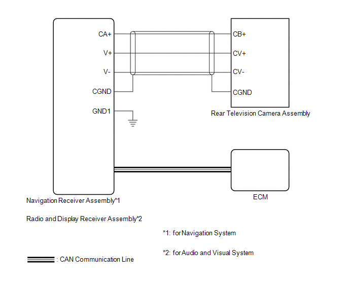 Communication Table
|
Sender |
Receiver |
Signal |
Line |
|---|---|---|---|
|
ECM |
|
Reverse signal |
CAN Communication Line |
- *1: for Navigation System
- *2: for Audio and Visual System
 Parts Location
PARTS LOCATION
ILLUSTRATION
ILLUSTRATION
...
 How To Proceed With Troubleshooting
CAUTION / NOTICE / HINT
HINT:
Use the following procedure to troubleshoot the rear view monitor system.
*: Use the Techstream.
PROCEDURE
1.
VEHICLE BROU ...
Other materials about Toyota Venza:
Air Conditioning Control Panel Circuit
DESCRIPTION
This circuit consists of the air conditioning control assembly and the A/C amplifier.
When the air conditioning control assembly is operated, signals are transmitted
to the A/C amplifier through the LIN communication system.
If the LIN commun ...
How To Proceed With Troubleshooting
CAUTION / NOTICE / HINT
HINT:
Use the following procedures to troubleshoot the power back door system.
*: Use the Techstream.
PROCEDURE
1.
VEHICLE BROUGHT TO WORKSHOP
NEXT
...
Key-off Operation Function Operates even if Operating Conditions are not Satisfied
DESCRIPTION
When the front doors are closed, each power window regulator motor assembly
can control its power window operation for approximately 45 seconds after
the ignition switch is turned from ON to off by receiving operation permission
...

0.1738