Toyota Venza: System Diagram
SYSTEM DIAGRAM
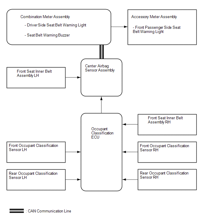 Communication Table
|
Sender |
Receiver |
Signal |
Communication Method |
|---|---|---|---|
|
Center airbag sensor assembly |
Combination meter assembly |
|
CAN |
 System Description
SYSTEM DESCRIPTION
1. SEAT BELT WARNING SYSTEM DESCRIPTION
If a seat belt is not fastened, this system flashes the seat belt warning light
or sounds the seat belt warning buzzer as a reminder.
(a ...
 How To Proceed With Troubleshooting
CAUTION / NOTICE / HINT
HINT:
Use these procedure to troubleshoot the seat belt warning system.
*: Use the Techstream.
PROCEDURE
1.
VEHICLE BROUGHT TO W ...
Other materials about Toyota Venza:
A/C ECU Vehicle Information Reading/Writing Processor Malfunction (B15F5)
DESCRIPTION
This DTC is stored when items controlled by the air conditioning amplifier assembly
cannot be customized via the audio and visual system vehicle customization screen.
HINT:
The air conditioning amplifier assembly controls the air conditioning ...
Screen Flicker or Color Distortion
PROCEDURE
1.
CHECK DISPLAY SETTING
(a) Reset display settings (contrast, brightness) and check that the screen appears
normal.
OK:
The display returns to normal.
OK
END
NG
...
Rear Light Assembly
Components
COMPONENTS
ILLUSTRATION
On-vehicle Inspection
ON-VEHICLE INSPECTION
PROCEDURE
1. INSPECT REAR LIGHT ASSEMBLY
(a) Disconnect the connector from the rear light assembly.
(b) Measu ...

0.1441