Toyota Venza: System Diagram
SYSTEM DIAGRAM
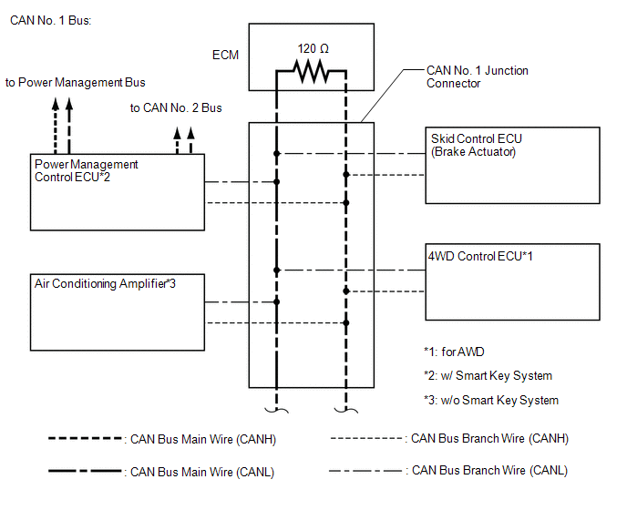
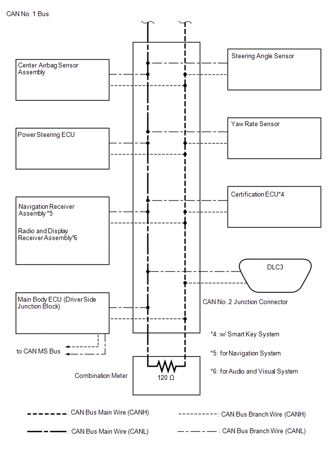
1. CAN NO. 1 BUS
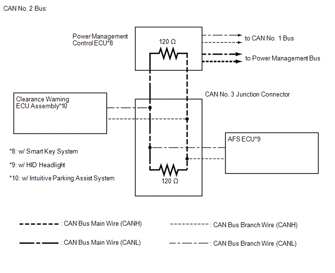
2. CAN NO. 2 BUS
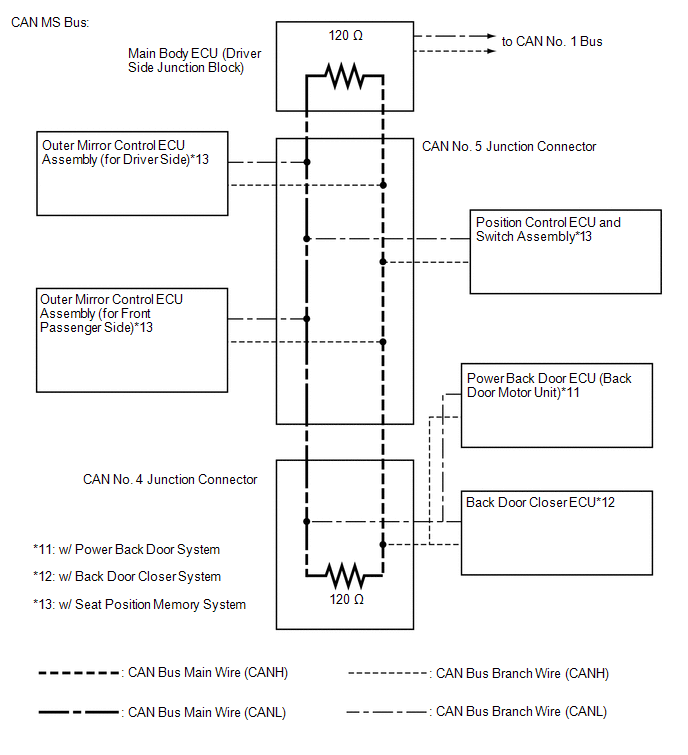
3. CAN MS BUS
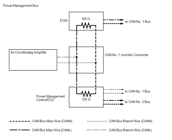
4. POWER MANAGEMENT BUS (w/ Smart Key System)
 Precaution
PRECAUTION
1. PRECAUTION FOR DISCONNECTING BATTERY CABLE
NOTICE:
When disconnecting the cable from the negative (-) battery terminal, initialize
the following systems after the cable is reconnect ...
 How To Proceed With Troubleshooting
CAUTION / NOTICE / HINT
PRECAUTIONS WHEN TROUBLESHOOTING
NOTICE:
DTCs for the CAN communication system are as follows: U0073, U0100,
U0101, U0123, U0124, U0126, U0129, U0131, U0142, U01 ...
Other materials about Toyota Venza:
Center Power Outlet Socket
Components
COMPONENTS
ILLUSTRATION
Installation
INSTALLATION
PROCEDURE
1. INSTALL CENTER POWER OUTLET SOCKET COVER
(a) Engage the 2 claws to install the center power outlet socket cover.
2 ...
Installation
INSTALLATION
PROCEDURE
1. INSTALL STEERING INTERMEDIATE SHAFT ASSEMBLY
(a) Align the matchmarks on the steering intermediate shaft assembly
and the steering column assembly.
Text in Illustration
*1
Matc ...
Installation
INSTALLATION
CAUTION / NOTICE / HINT
HINT:
Perform "Inspection After Repair" after replacing the camshaft, No. 2 camshaft,
camshaft timing gear assembly, camshaft timing exhaust gear assembly or cylinder
head sub-assembly (See page ).
PROCED ...

0.1673