Toyota Venza: System Diagram
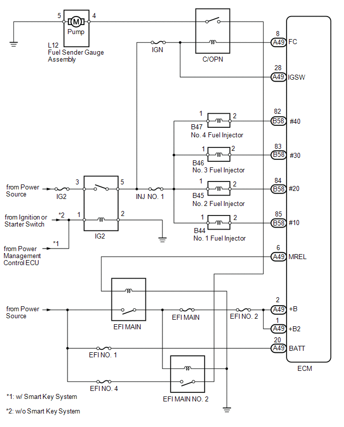
SYSTEM DIAGRAM
 On-vehicle Inspection
ON-VEHICLE INSPECTION
PROCEDURE
1. CHECK FOR FUEL PUMP OPERATION AND INSPECT FOR FUEL LEAK
(a) Check fuel pump operation.
(1) Connect the Techstream to the DLC3.
(2) Turn the ignition switch to O ...
 Fuel Tank
...
Other materials about Toyota Venza:
Installation
INSTALLATION
PROCEDURE
1. INSTALL FRONT SHOULDER BELT ANCHOR ADJUSTER ASSEMBLY
(a) Engage the adjuster positioning hole with the guide and install the
front shoulder belt anchor adjuster assembly with the 2 bolts.
Torque:
42 N·m {428 ...
Removal
REMOVAL
PROCEDURE
1. REMOVE AIR CONDITIONING UNIT ASSEMBLY
(See page )
2. REMOVE NO. 1 FINISH PANEL MOUNTING BRACKET
3. REMOVE NO. 2 FINISH PANEL MOUNTING BRACKET
4. REMOVE NO. 3 AIR DUCT SUB-ASSEMBLY
5. REMOVE NO. 2 AIR DUCT SUB-ASSEMBLY
...
Lost Communication with A/C ECU (U0164)
DESCRIPTION
DTC No.
DTC Detection Condition
Trouble Area
U0164
No communication from the air conditioning amplifier continues.
Air conditioning amplifier branch wire or connect ...

0.168