Toyota Venza: Speaker Output Short (B15C3)
DESCRIPTION
This DTC is stored when a malfunction occurs in the speakers.
|
DTC No. |
DTC Detection Condition |
Trouble Area |
|---|---|---|
|
B15C3 |
A short is detected in the speaker output circuit. |
|
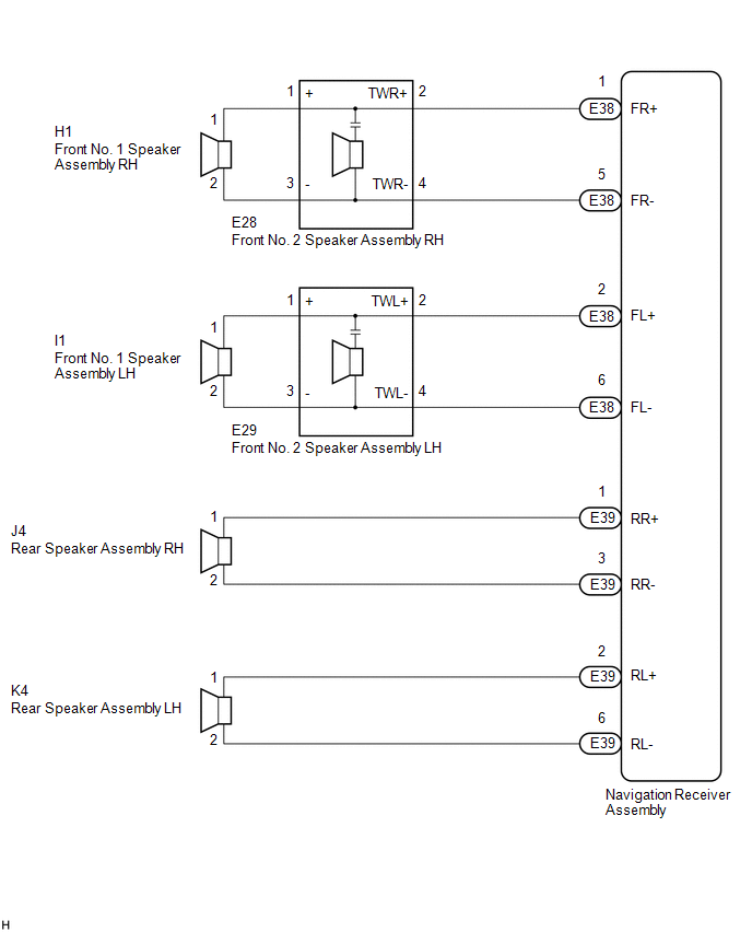
- *1: for 6 Speakers
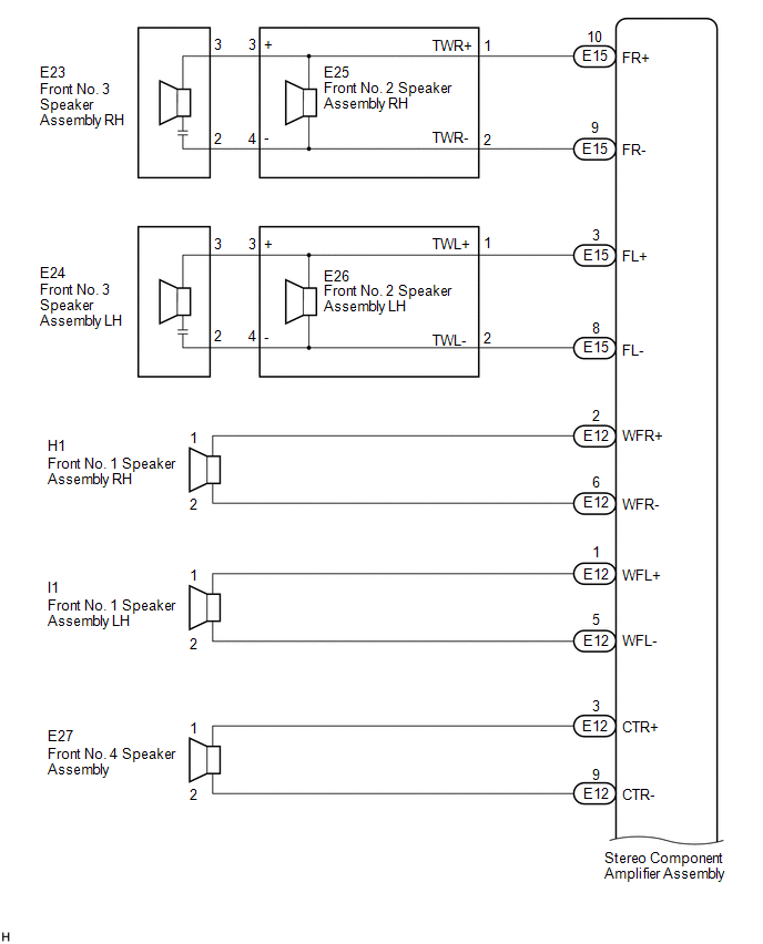
- *2: for 13 Speakers
WIRING DIAGRAM
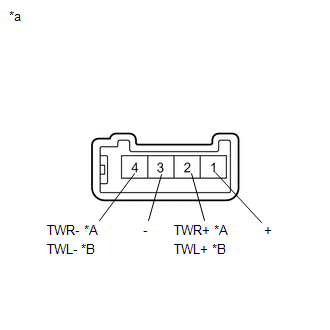
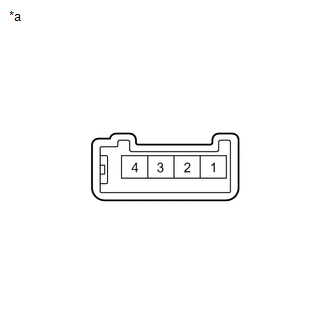
1. for 6 Speakers
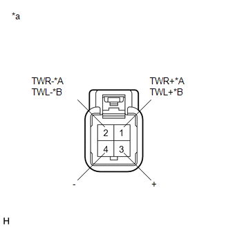
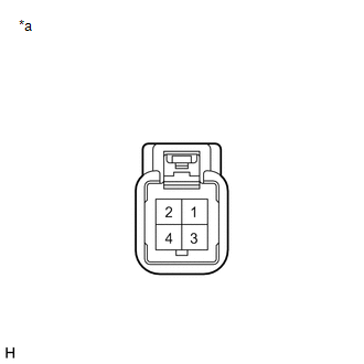
2. for 13 Speakers
PROCEDURE
|
1. |
CONFIRM MODEL |
(a) Choose the model to be inspected.
|
Result |
Proceed to |
|---|---|
|
for 6 Speakers |
A |
|
for 13 Speakers |
B |
| B | .gif) |
GO TO STEP 8 |
|
.gif)
|
2. |
CHECK HARNESS AND CONNECTOR (NAVIGATION RECEIVER ASSEMBLY - BODY GROUND) |
(a) Disconnect the E38 and E39 navigation receiver assembly connectors.
(b) Disconnect the E28 and E29 front No. 2 speaker assembly connectors.
(c) Disconnect the J4 and K4 rear speaker assembly connectors.
(d) Measure the resistance between the navigation receiver assembly and body ground to check for a short circuit in the wire harness.
Standard Resistance:
|
Tester Connection |
Condition |
Specified Condition |
|---|---|---|
|
E38-1 (FR+) - Body ground |
Always |
10 kΩ or higher |
|
E38-5 (FR-) - Body ground |
Always |
10 kΩ or higher |
|
E38-2 (FL+) - Body ground |
Always |
10 kΩ or higher |
|
E38-6 (FL-) - Body ground |
Always |
10 kΩ or higher |
|
E39-1 (RR+) - Body ground |
Always |
10 kΩ or higher |
|
E39-3 (RR-) - Body ground |
Always |
10 kΩ or higher |
|
E39-2 (RL+) - Body ground |
Always |
10 kΩ or higher |
|
E39-6 (RL-) - Body ground |
Always |
10 kΩ or higher |
| NG | |
REPAIR OR REPLACE HARNESS OR CONNECTOR |
|
|
3. |
CHECK HARNESS AND CONNECTOR (FRONT NO. 2 SPEAKER ASSEMBLY - BODY GROUND) |
(a) Disconnect the E28 and E29 front No. 2 speaker assembly connectors.
(b) Disconnect the H1 and I1 front No. 1 speaker assembly connectors.
(c) Measure the resistance between each of the front No. 2 speaker assemblies and body ground to check for a short circuit in the wire harness.
Standard Resistance:
|
Tester Connection |
Condition |
Specified Condition |
|---|---|---|
|
E28-3 (-) - Body ground |
Always |
10 kΩ or higher |
|
E28-1 (+) - Body ground |
Always |
10 kΩ or higher |
|
E29-3 (-) - Body ground |
Always |
10 kΩ or higher |
|
E29-1 (+) - Body ground |
Always |
10 kΩ or higher |
| NG | |
REPAIR OR REPLACE HARNESS OR CONNECTOR |
|
|
4. |
INSPECT FRONT NO. 1 SPEAKER ASSEMBLY |
(a) Remove the front No. 1 speaker assembly (See page
.gif) ).
).
|
(b) Measure the resistance according to the value(s) in the table below. Standard Resistance:
|
|
| NG | |
REPLACE FRONT NO. 1 SPEAKER ASSEMBLY |
|
|
5. |
INSPECT FRONT NO. 2 SPEAKER ASSEMBLY |
(a) Remove the front No. 2 speaker assembly (See page
).
|
(b) Measure the resistance according to the value(s) in the table below. Standard Resistance: for RH:
|
|
| NG | |
REPLACE FRONT NO. 2 SPEAKER ASSEMBLY |
|
|
6. |
REPLACE FRONT NO. 2 SPEAKER ASSEMBLY |
(a) Replace the front No. 2 speaker assembly with a new or known good one (See
page ).
(b) Clear the DTCs (See page ).
(c) Recheck for DTCs and check that no DTCs are output.
OK:
No DTCs are output.
HINT:
- Connect all the connectors to the front No. 2 speaker assemblies that were disconnected.
- When there is a possibility that either the right or left front No. 2 speaker assembly is defective, inspect by interchanging the right one with the left one.
- Perform the above inspection on both the LH and RH side.
| OK | |
END |
|
|
7. |
INSPECT REAR SPEAKER ASSEMBLY |
(a) Remove the rear speaker assembly (See page
).
|
(b) Measure the resistance according to the value(s) in the table below. Standard Resistance:
|
|
| OK | |
REPLACE NAVIGATION RECEIVER ASSEMBLY |
| NG | |
REPLACE REAR SPEAKER ASSEMBLY |
|
8. |
CHECK HARNESS AND CONNECTOR (STEREO COMPONENT AMPLIFIER ASSEMBLY - BODY GROUND) |
(a) Disconnect the E12 and E15 stereo component amplifier assembly connectors.
(b) Disconnect the E25 and E26 front No. 2 speaker assembly connectors.
(c) Disconnect the H1 and I1 front No. 1 speaker assembly connectors.
(d) Disconnect the E27 front No. 4 speaker assembly connector.
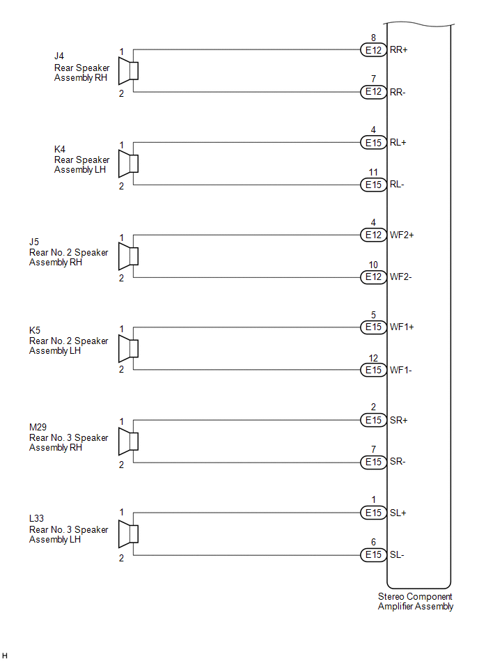
(e) Disconnect the J4 and K4 rear speaker assembly connectors.
(f) Disconnect the J5 and K5 rear No. 2 speaker assembly connectors.
(g) Disconnect the M29 and L33 rear No. 3 speaker assembly connectors.
(h) Measure the resistance between the stereo component amplifier assembly and body ground to check for a short circuit in the wire harness.
Standard Resistance:
|
Tester Connection |
Condition |
Specified Condition |
|---|---|---|
|
E15-10 (FR+) - Body ground |
Always |
10 kΩ or higher |
|
E15-9 (FR-) - Body ground |
Always |
10 kΩ or higher |
|
E15-3 (FL+) - Body ground |
Always |
10 kΩ or higher |
|
E15-8 (FL-) - Body ground |
Always |
10 kΩ or higher |
|
E12-2 (WFR+) - Body ground |
Always |
10 kΩ or higher |
|
E12-6 (WFR-) - Body ground |
Always |
10 kΩ or higher |
|
E12-1 (WFL+) - Body ground |
Always |
10 kΩ or higher |
|
E12-5 (WFL-) - Body ground |
Always |
10 kΩ or higher |
|
E12-3 (CTR+) - Body ground |
Always |
10 kΩ or higher |
|
E12-9 (CTR-) - Body ground |
Always |
10 kΩ or higher |
|
E12-8 (RR+) - Body ground |
Always |
10 kΩ or higher |
|
E12-7 (RR-) - Body ground |
Always |
10 kΩ or higher |
|
E15-4 (RL+) - Body ground |
Always |
10 kΩ or higher |
|
E15-11 (RL-) - Body ground |
Always |
10 kΩ or higher |
|
E12-4 (WF2+) - Body ground |
Always |
10 kΩ or higher |
|
E12-10 (WF2-) - Body ground |
Always |
10 kΩ or higher |
|
E15-5 (WF1+) - Body ground |
Always |
10 kΩ or higher |
|
E15-12 (WF1-) - Body ground |
Always |
10 kΩ or higher |
|
E15-2 (SR+) - Body ground |
Always |
10 kΩ or higher |
|
E15-7 (SR-) - Body ground |
Always |
10 kΩ or higher |
|
E15-1 (SL+) - Body ground |
Always |
10 kΩ or higher |
|
E15-6 (SL-) - Body ground |
Always |
10 kΩ or higher |
| NG | |
REPAIR OR REPLACE HARNESS OR CONNECTOR |
|
|
9. |
CHECK HARNESS AND CONNECTOR (FRONT NO. 2 SPEAKER ASSEMBLY - BODY GROUND) |
(a) Disconnect the E23 and E24 front No. 3 speaker assembly connectors.
(b) Disconnect the E25 and E26 front No. 2 speaker assembly connectors.
(c) Measure the resistance between each of the front No. 2 speaker assemblies and body ground to check for a short circuit in the wire harness.
Standard Resistance:
|
Tester Connection |
Condition |
Specified Condition |
|---|---|---|
|
E25-3 (+) - Body ground |
Always |
10 kΩ or higher |
|
E25-4 (-) - Body ground |
Always |
10 kΩ or higher |
|
E26-3 (+) - Body ground |
Always |
10 kΩ or higher |
|
E26-4 (-) - Body ground |
Always |
10 kΩ or higher |
| NG | |
REPAIR OR REPLACE HARNESS OR CONNECTOR |
|
|
10. |
INSPECT FRONT NO. 3 SPEAKER ASSEMBLY |
(a) Remove the front No. 3 speaker assembly (See page
).
|
(b) Measure the resistance according to the value(s) in the table below. Standard Resistance:
|
|
| NG | |
REPLACE FRONT NO. 3 SPEAKER ASSEMBLY |
|
|
11. |
REPLACE FRONT NO. 3 SPEAKER ASSEMBLY |
(a) Replace the front No. 3 speaker assembly with a new or known good one (See
page ).
(b) Clear the DTCs (See page ).
(c) Recheck for DTCs and check that no DTCs are output.
OK:
No DTCs are output.
HINT:
- Connect all the connectors to the front No. 3 speaker assemblies that were disconnected.
- When there is a possibility that either the right or left front No. 3 speaker assembly is defective, inspect by interchanging the right one with the left one.
- Perform the above inspection on both the LH and RH side.
| OK | |
END |
|
|
12. |
INSPECT FRONT NO. 2 SPEAKER ASSEMBLY |
(a) Remove the front No. 2 speaker assembly (See page
).
|
(b) Measure the resistance according to the value(s) in the table below. Standard Resistance: for RH:
|
|
| NG | |
REPLACE FRONT NO. 2 SPEAKER ASSEMBLY |
|
|
13. |
INSPECT FRONT NO. 1 SPEAKER ASSEMBLY |
(a) Remove the front No. 1 speaker assembly (See page
).
|
(b) Measure the resistance according to the value(s) in the table below. Standard Resistance:
|
|
| NG | |
REPLACE FRONT NO. 1 SPEAKER ASSEMBLY |
|
|
14. |
INSPECT FRONT NO. 4 SPEAKER ASSEMBLY |
(a) Remove the front No. 4 speaker assembly (See page
).
|
(b) Measure the resistance according to the value(s) in the table below. Standard Resistance:
|
|
| NG | |
REPLACE FRONT NO. 4 SPEAKER ASSEMBLY |
|
|
15. |
INSPECT REAR SPEAKER ASSEMBLY |
(a) Remove the rear speaker assembly (See page
).
|
(b) Measure the resistance according to the value(s) in the table below. Standard Resistance:
|
|
| NG | |
REPLACE REAR SPEAKER ASSEMBLY |
|
|
16. |
INSPECT REAR NO. 2 SPEAKER ASSEMBLY |
(a) Remove the rear No. 2 speaker assembly (See page
).
|
(b) Measure the resistance according to the value(s) in the table below. Standard Resistance:
|
|
.png)
| NG | |
REPLACE REAR NO. 2 SPEAKER ASSEMBLY |
|
|
17. |
INSPECT REAR NO. 3 SPEAKER ASSEMBLY |
(a) Remove the rear No. 3 speaker assembly (See page
).
|
(b) Measure the resistance according to the value(s) in the table below. Standard Resistance:
|
|
| OK | |
REPLACE STEREO COMPONENT AMPLIFIER ASSEMBLY |
| NG | |
REPLACE REAR NO. 3 SPEAKER ASSEMBLY |
 Speed Signal Malfunction (B15C2)
DESCRIPTION
The navigation receiver assembly receives a vehicle speed signal from the combination
meter assembly and information from the navigation antenna assembly, and then adjusts
the vehicle ...
 Stereo Component Amplifier Disconnected (B15D3)
DESCRIPTION
The navigation receiver assembly and stereo component amplifier assembly are
connected via AVC-LAN communication.
This DTC is stored when an AVC-LAN communication error occurs between ...
Other materials about Toyota Venza:
Cruise SET Indicator Light Circuit
DESCRIPTION
The ECM detects a cruise control switch signal and sends it to the combination
meter assembly through CAN. Then the SET indicator light comes on.
The SET indicator light circuit uses CAN for communication. If there
is a malfunct ...
Removal
REMOVAL
PROCEDURE
1. REMOVE REAR WHEELS
2. REMOVE REAR STABILIZER LINK ASSEMBLY LH
(a) Remove the nut and separate the rear stabilizer link assembly LH
from the rear stabilizer bar.
Text in Illustration
*1
...
Cellular Phone Registration Failure
PROCEDURE
1.
CHECK USAGE CONDITION
(a) Check that the vehicle and cellular phone meet the following conditions:
NOTICE:
If changing cellular phone settings, updating software, etc. is necessary, make
sure to obtain the per ...

0.139