Toyota Venza: Driver Side Power Mirror cannot be Adjusted with Power Mirror Switch
SYSTEM DESCRIPTION
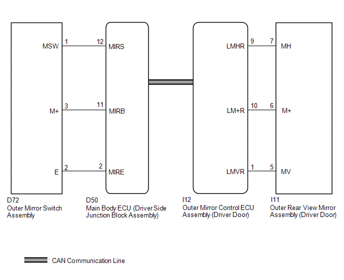
When the mirror adjust switch is operated, the main body ECU (driver side junction block assembly) detects the switch operation and sends the mirror adjust switch signal to the outer mirror control ECU assembly (driver door) via CAN communication. On receiving the signal, the outer mirror control ECU assembly (driver door) operates the vertical and horizontal mirror motors, which are built into the outer rear view mirror assembly (driver door), to adjust the mirror surface position.
WIRING DIAGRAM
PROCEDURE
|
1. |
CHECK CAN COMMUNICATION SYSTEM |
(a) Check for CAN communication system DTCs (See page
.gif) ).
).
OK:
CAN communication DTC is not output.
| NG | .gif) |
GO TO CAN COMMUNICATION SYSTEM (DIAGNOSTIC TROUBLE CODE CHART) |
|
.gif)
|
2. |
READ VALUE USING TECHSTREAM (OUTER MIRROR SWITCH ASSEMBLY) |
(a) Connect the Techstream to the DLC3.
(b) Turn the ignition switch ON.
(c) Turn the Techstream on.
(d) Enter the following menus: Body Electrical / Main Body / Data List.
(e) Read the Data List according to the display on the Techstream.
Main Body|
Tester Display |
Measurement Item/Range |
Normal Condition |
Diagnostic Note |
|---|---|---|---|
|
Mirror Selection SW (L) |
Mirror select switch signal for LH mirror / ON or OFF |
ON: Mirror select switch in L position OFF: Mirror select switch off or in R position |
- |
|
Mirror Position SW (R) |
Mirror adjust switch signal (Right) / ON or OFF |
ON: Mirror adjust switch pressed right OFF: Mirror adjust switch not pressed right |
Check with the mirror select switch in the L position. |
|
Mirror Position SW (L) |
Mirror adjust switch signal (Left) / ON or OFF |
ON: Mirror adjust switch pressed left OFF: Mirror adjust switch not pressed left |
Check with the mirror select switch in the L position. |
|
Mirror Position SW (Up) |
Mirror adjust switch signal (Up) / ON or OFF |
ON: Mirror adjust switch pressed up OFF: Mirror adjust switch not pressed up |
Check with the mirror select switch in the L position. |
|
Mirror Position SW (Dwn) |
Mirror adjust switch signal (Down) / ON or OFF |
ON: Mirror adjust switch pressed down OFF: Mirror adjust switch not pressed down |
Check with the mirror select switch in the L position. |
OK:
On the Techstream screen, ON or OFF is displayed for each item according to the table above.
| NG | |
GO TO STEP 6 |
|
|
3. |
PERFORM ACTIVE TEST USING TECHSTREAM (POWER MIRROR CONTROL FUNCTION) |
(a) Enter the following menus: Body Electrical / Mirror L / Active Test.
(b) Perform the Active Test according to the display on the Techstream.
Mirror L|
Tester Display |
Test Part |
Control Range |
Diagnostic Note |
|---|---|---|---|
|
Mirror Up/Down |
Mirror vertical operation |
Up / Down |
|
|
Mirror Right/Left |
Mirror horizontal operation |
Right / Left |
|
OK:
Power mirror operation is normal.
| OK | |
REPLACE OUTER MIRROR CONTROL ECU ASSEMBLY (DRIVER DOOR) |
|
|
4. |
INSPECT OUTER REAR VIEW MIRROR ASSEMBLY (DRIVER DOOR) |
|
(a) Remove the outer rear view mirror assembly (driver door) (See page
(1) Apply battery voltage and check the operation of the outer rear view mirror assembly (driver door). OK:
|
|
| NG | |
REPLACE OUTER REAR VIEW MIRROR ASSEMBLY (DRIVER DOOR) |
|
|
5. |
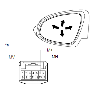
CHECK HARNESS AND CONNECTOR (OUTER REAR VIEW MIRROR ASSEMBLY (DRIVER DOOR) - OUTER MIRROR CONTROL ECU ASSEMBLY (DRIVER DOOR)) |
(a) Disconnect the I11 connector from the outer rear view mirror assembly (driver door).
(b) Disconnect the I12 connector from the outer mirror control ECU assembly (driver door).
(c) Measure the resistance according to the value(s) in the table below.
Standard Resistance:
|
Tester Connection |
Condition |
Specified Condition |
|---|---|---|
|
I12-9 (LMHR) - I11-7 (MH) |
Always |
Below 1 Ω |
|
I12-10 (LM+R) - I11-6 (M+) |
Always |
Below 1 Ω |
|
I12-1 (LMVR) - I11-5 (MV) |
Always |
Below 1 Ω |
|
I12-9 (LMHR) - Body ground |
Always |
10 kΩ or higher |
|
I12-10 (LM+R) - Body ground |
Always |
10 kΩ or higher |
|
I12-1 (LMVR) - Body ground |
Always |
10 kΩ or higher |
| OK | |
REPLACE OUTER MIRROR CONTROL ECU ASSEMBLY (DRIVER DOOR) |
| NG | |
REPAIR OR REPLACE HARNESS OR CONNECTOR |
|
6. |
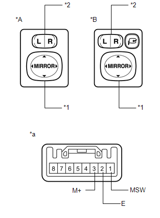
INSPECT OUTER MIRROR SWITCH ASSEMBLY |
|
(a) Remove the outer mirror switch assembly (See page
|
|
(b) Measure the resistance according to the value(s) in the table below.
Standard Resistance:
|
Tester Connection |
Condition |
Specified Condition |
|---|---|---|
|
3 (M+) - 2 (E) |
Mirror adjust switch pressed up |
90 to 110 Ω |
|
Mirror adjust switch pressed down |
437 to 503 Ω |
|
|
Mirror adjust switch pressed left |
744 to 856 Ω |
|
|
Mirror adjust switch pressed right |
225 to 275 Ω |
|
|
1 (MSW) - 2 (E) |
Mirror select switch L |
90 to 110 Ω |
|
Mirror select switch R |
Below 10 Ω |
|
|
Mirror select switch off |
10 kΩ or higher |
|
*A |
w/o Retract Mirror |
|
*B |
w/ Retract Mirror |
|
*1 |
Mirror Adjust Switch |
|
*2 |
Mirror Select Switch |
|
*a |
Component without harness connected (Outer Mirror Switch Assembly) |
| NG | |
REPLACE OUTER MIRROR SWITCH ASSEMBLY |
|
|
7. |
CHECK HARNESS AND CONNECTOR (OUTER MIRROR SWITCH - MAIN BODY ECU (DRIVER SIDE JUNCTION BLOCK ASSEMBLY)) |
(a) Disconnect the D72 connector from the outer mirror switch assembly.
(b) Disconnect the D50 connector from the main body ECU (driver side junction block assembly).
(c) Measure the resistance according to the value(s) in the table below.
Standard Resistance:
|
Tester Connection |
Condition |
Specified Condition |
|---|---|---|
|
D72-2 (E) - D50-2 (MIRE) |
Always |
Below 1 Ω |
|
D72-3 (M+) - D50-11 (MIRB) |
Always |
Below 1 Ω |
|
D72-1 (MSW) - D50-12 (MIRS) |
Always |
Below 1 Ω |
|
D72-2 (E) - Body ground |
Always |
10 kΩ or higher |
|
D72-3 (M+) - Body ground |
Always |
10 kΩ or higher |
|
D72-1 (MSW) - Body ground |
Always |
10 kΩ or higher |
| OK | |
REPLACE MAIN BODY ECU (DRIVER SIDE JUNCTION BLOCK ASSEMBLY) |
| NG | |
REPAIR OR REPLACE HARNESS OR CONNECTOR |
 Diagnosis System
DIAGNOSIS SYSTEM
1. DESCRIPTION
(a) Data of the system can be read from the Data Link Connector 3 (DLC3) of the
vehicle. Therefore, when the system seems to be malfunctioning, use the Techstream
...
 Front Passenger Side Power Mirror cannot be Adjusted with Power Mirror Switch
SYSTEM DESCRIPTION
When the mirror adjust switch is operated, the main body ECU (driver side junction
block assembly) detects the switch operation and sends the mirror adjust switch
signal to the ...
Other materials about Toyota Venza:
Diagnostic Trouble Code Chart
DIAGNOSTIC TROUBLE CODE CHART
Navigation System
DTC Code
Detection Item
See page
B1532
LVDS Signal Malfunction (from Extension Module)
B1551
HD Radio Tuner ...
Front Occupant Classification Sensor RH Collision Detection (B1786)
DESCRIPTION
DTC B1786 is output when the occupant classification ECU receives a collision
detection signal sent by the front occupant classification sensor RH if an accident
occurs.
DTC B1786 is also output when the front seat assembly RH is subjected to ...
Radio Broadcast cannot be Received or Poor Reception
PROCEDURE
1.
CHECK NAVIGATION RECEIVER ASSEMBLY
(a) Check the radio automatic station search function.
(1) Check the radio automatic station search function by activating it.
Result
Proceed to
...

0.1157