Toyota Venza: Components
COMPONENTS
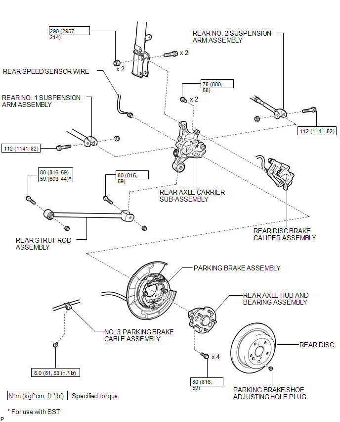
ILLUSTRATION

 Removal
REMOVAL
CAUTION / NOTICE / HINT
HINT:
Use the same procedure for the RH side and LH side.
The procedure listed below is for the LH side.
PROCEDURE
1. REMOVE REAR WHEEL
2. SEPAR ...
Other materials about Toyota Venza:
Tongue Plate Stopper
Components
COMPONENTS
ILLUSTRATION
Replacement
REPLACEMENT
PROCEDURE
1. REMOVE TONGUE PLATE STOPPER
(a) Slide the tongue plate above the installation position of the tongue
plate stopper, and temporarily hold it with adhesive tape.
...
Precaution
PRECAUTION
1. PRECAUTION FOR DISCONNECTING CABLE FROM NEGATIVE BATTERY TERMINAL
NOTICE:
When disconnecting the cable from the negative (-) battery terminal, initialize
the following system(s) after the cable is reconnected.
System Name
...
Linear Solenoid Circuit (C1298/98)
DESCRIPTION
The AWD control ECU receives signals from each sensor to control clutch pressure
to distribute torque according to the driving conditions.
DTC No.
DTC Detection Condition
Trouble Area
C1298/98
...

0.1149