Toyota Venza: Removal
REMOVAL
CAUTION / NOTICE / HINT
HINT:
- Use the same procedure for the RH side and LH side.
- The procedure listed below is for the LH side.
PROCEDURE
1. PRECAUTION
CAUTION:
Be sure to read Precaution thoroughly before servicing (See page
.gif) ).
).
2. DISCONNECT CABLE FROM NEGATIVE BATTERY TERMINAL
CAUTION:
Wait at least 90 seconds after disconnecting the cable from the negative (-) battery terminal to disable the SRS system.
NOTICE:
When disconnecting the cable, some systems need to be initialized after the cable
is reconnected (See page ).
3. REMOVE ROOF HEADLINING ASSEMBLY
HINT:
Refer to the procedure up to Remove Roof Headlining Assembly (See page
).
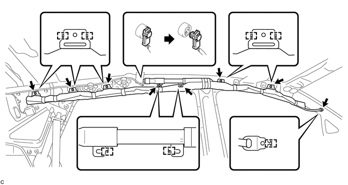
4. REMOVE CURTAIN SHIELD AIRBAG ASSEMBLY
CAUTION:
When storing the curtain shield airbag assembly, keep the airbag deployment side facing upward.
(a) Check that the ignition switch is off.
(b) Check that the cable is disconnected from the negative (-) battery terminal.
CAUTION:
Wait at least 90 seconds after disconnecting the cable from the negative (-) battery terminal to disable the SRS system.
(c) Using a screwdriver with the tip wrapped with protective tape, disconnect the curtain shield airbag connector.
NOTICE:
When disconnecting the airbag connector, take care not to damage the airbag wire harness.
(d) Remove the 8 bolts.
(e) Disengage the 13 hooks to remove the curtain shield airbag assembly.
 On-vehicle Inspection
ON-VEHICLE INSPECTION
CAUTION / NOTICE / HINT
CAUTION:
Be sure to follow the correct removal and installation procedures of the curtain
shield airbag assembly.
PROCEDURE
1. INSPECT CURTAIN SHIE ...
 Installation
INSTALLATION
CAUTION / NOTICE / HINT
HINT:
Use the same procedure for the RH side and LH side.
The procedure listed below is for the LH side.
PROCEDURE
1. INSTALL CURTAIN SHIELD ...
Other materials about Toyota Venza:
Removal
REMOVAL
PROCEDURE
1. DRAIN AUTOMATIC TRANSAXLE FLUID
2. REMOVE FRONT FRAME ASSEMBLY
See page
3. SUPPORT ENGINE ASSEMBLY
4. REMOVE BELT
5. REMOVE AUTOMATIC TRANSAXLE OIL PAN SUB-ASSEMBLY
(a) Remove the 18 bolts and automatic transa ...
Engine Oil Cooler
Components
COMPONENTS
ILLUSTRATION
Removal
REMOVAL
PROCEDURE
1. REMOVE EXHAUST MANIFOLD ASSEMBLY
HINT:
See page
2. DRAIN ENGINE OIL
3. DRAIN ENGINE COOLANT
4. REMOVE OIL COOLER ASSEMBLY
(a) Remove the nut, union bolt, seal ...
How To Use This Manual
General Information
GENERAL INFORMATION
1. GENERAL DESCRIPTION
(a) This manual is written in accordance with SAE J2008.
(b) Repair operations can be separated mainly into the following 3 processes:
(1) Diagnosis
(2) Removing / Installing, Replacing, Di ...

0.1226