
Toyota Venza: Rear window defogger
Clear the rear window using the defogger.
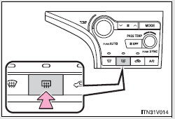
On/off
The defogger will automatically turn off after 15 or 60 minutes.
This operation time changes according to the ambient temperature and vehicle speed.
Pressing the switch again also turns the defogger off.
- The rear window defogger can be operated when
►Vehicles with smart key system The “ENGINE START STOP” switch is in IGNITION ON mode.
►Vehicles without smart key system The engine switch is in the “ON” position.
- Outside rear view mirror defoggers and windshield wiper de-icer
Turning the rear window defogger on will turn the outside rear view mirror defoggers and the windshield wiper de-icer on.
The outside rear view mirror is used to remove raindrops, dew and frost from the outside rear view mirrors.
The windshield wiper de-icer is used to prevent ice from building up on the windshield and wiper blades.
CAUTION
- Outside rear view mirror defoggers and windshield wiper de-icer
Do not touch the rear view mirror surfaces, the glass at the lower part of the windshield or to the side of the front pillars, as they can become very hot and burn you.
NOTICE
- To prevent battery discharge
Turn the defoggers off when the engine is not running.
 Adjusting the position and opening and closing the air outlets
► Front center outlets
Direct air flow to the left or right, up or down.
►Front side outlets
1. Direct air flow to the left or right, up or down.
2. Turn the knob to open or close ...

Other materials about Toyota Venza:
Inspection
INSPECTION
PROCEDURE
1. INSPECT INTEGRATION RELAY
(a) Inner circuit (for 2GR-FE)
(1) for EFI MAIN relay
Measure the resistance according to the value(s) in the table
below.
Standard Resistance:
...
Sound Signal Circuit between Navigation Receiver Assembly and Stereo Jack Adapter
DESCRIPTION
The No. 1 stereo jack adapter assembly sends the sound signal from an external
device to the navigation receiver assembly via this circuit.
The sound signal that has been sent is amplified by the navigation receiver assembly
and then is sent ...
On-vehicle Inspection
ON-VEHICLE INSPECTION
PROCEDURE
1. INSPECT REAR WIPER MOTOR AND BRACKET ASSEMBLY
(a) Operate the rear wiper motor and bracket assembly.
(b) Stop the rear wiper motor and bracket assembly operation.
...

0.1622