Toyota Venza: Power Back Door cannot be Opened or Closed Using the Power Back Door Switch
DESCRIPTION
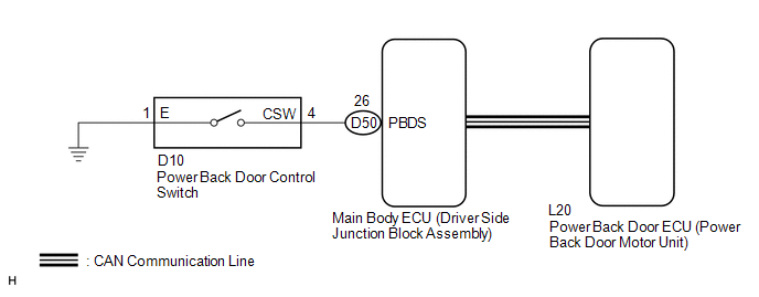
When the power back door cannot be opened or closed using the power back door control switch, one of the following may be malfunctioning: 1) power back door control switch circuit, 2) power back door ECU (power back door motor unit) or 3) main body ECU (driver side junction block assembly).
WIRING DIAGRAM
CAUTION / NOTICE / HINT
CAUTION:
The power back door system uses a CAN communication system. Inspect the communication
function by following How to Proceed with Troubleshooting (See page
.gif) ). Troubleshoot the power back door system after
). Troubleshoot the power back door system after
confirming that the communication system is functioning properly.
PROCEDURE
|
1. |
READ VALUE USING TECHSTREAM (POWER BACK DOOR CONTROL SWITCH) |
(a) Connect the Techstream to the DLC3.
(b) Turn the ignition switch to ON.
(c) Turn the Techstream on.
(d) Enter the following menus: Body Electrical / Main Body / Data List.
(e) Check the Data List to determine if the power back door control switch functions properly.
Main Body (Main Body ECU (Driver Side Junction Block Assembly))|
Tester Display |
Measurement Item/Range |
Normal Condition |
Diagnostic Note |
|---|---|---|---|
|
Back Door Open SW |
Power back door control switch / ON or OFF |
ON: Power back door control switch pushed OFF: Power back door control switch not pushed |
- |
OK:
The power back door control switch functions as specified in the normal condition column.
| NG | .gif) |
GO TO STEP 5 |
|
.gif)
|
2. |
REPLACE POWER BACK DOOR ECU (POWER BACK DOOR MOTOR UNIT) |
(a) Replace the power back door ECU (power back door motor unit) (See page
).
|
|
3. |
INITIALIZE POWER BACK DOOR ECU |
(a) Perform the initialization for the power back door ECU (power back door motor
unit) (See page ).
|
|
4. |
CHECK POWER BACK DOOR OPERATION |
(a) Check that the power back door operates normally (See page
).
OK:
Power back door operates normally.
| OK | |
END (POWER BACK DOOR ECU (POWER BACK DOOR MOTOR UNIT) WAS DEFECTIVE) |
| NG | |
REPLACE MAIN BODY ECU (DRIVER SIDE JUNCTION BLOCK ASSEMBLY) |
|
5. |
INSPECT POWER BACK DOOR CONTROL SWITCH |
|
(a) Remove the power back door control switch (See page
|
|
.png)
(b) Measure the resistance according to the value(s) in the table below.
Standard Resistance:
|
Tester Connection |
Switch Position |
Specified Condition |
|---|---|---|
|
1 (E) - 4 (CSW) |
Power back door control switch not pushed (off) |
10 kΩ or higher |
|
1 (E) - 4 (CSW) |
Power back door control switch pushed (on) |
Below 1 Ω |
| NG | |
REPLACE POWER BACK DOOR CONTROL SWITCH |
|
|
6. |
CHECK HARNESS AND CONNECTOR (POWER BACK DOOR CONTROL SWITCH - MAIN BODY ECU) |
|
(a) Disconnect the D10 power back door control switch and D50 main body ECU connectors. |
|
(b) Measure the resistance according to the value(s) in the table below.
Standard Resistance:
|
Tester Connection |
Condition |
Specified Condition |
|---|---|---|
|
D10-4 (CSW) - D50-26 (PBDS) |
Always |
Below 1 Ω |
|
D10-1 (E) - Body ground |
Always |
Below 1 Ω |
|
D10-4 (CSW) - Body ground |
Always |
10 kΩ or higher |
|
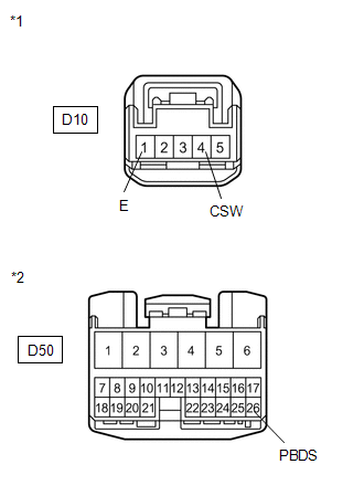
*1 |
Front view of wire harness connector (to Power Back Door Control Switch) |
|
*2 |
Front view of wire harness connector (to Main Body ECU) |
| OK | |
REPLACE MAIN BODY ECU (DRIVER SIDE JUNCTION BLOCK ASSEMBLY) |
| NG | |
REPAIR OR REPLACE HARNESS OR CONNECTOR |
 Back Door Motor Clutch Malfunction (B2225)
DESCRIPTION
When an electrical malfunction (open or short) is detected in the clutch circuit
of the power back door ECU (power back door motor unit) while the power back door
is operating, the po ...
 Power Back Door cannot be Operated Using Any Switch
DESCRIPTION
When the power back door cannot be operated using any switch, one of the following
may be the cause: 1) initialization of the power back door ECU (power back door
motor unit), 2) powe ...
Other materials about Toyota Venza:
Precaution
PRECAUTION
1. PRECAUTION FOR DISCONNECTING THE BATTERY CABLE
NOTICE:
When disconnecting the cable from the negative (-) battery terminal, initialize
the following systems after the cable is reconnected.
System Name
See Procedure
...
Occupant Classification Sensor Power Supply Circuit Malfunction (B1793)
DESCRIPTION
The occupant classification sensor power supply circuit consists of the occupant
classification ECU and occupant classification sensors.
DTC B1793 is recorded when a malfunction is detected in the occupant classification
sensor power supply c ...
Inspection
INSPECTION
PROCEDURE
1. INSPECT PARK/NEUTRAL POSITION SWITCH ASSEMBLY
(a) Measure the resistance according to the value(s) in the table below
when the shift lever is moved to each position.
Text in Illustration
*1
...

0.1408