Toyota Venza: Parts Location
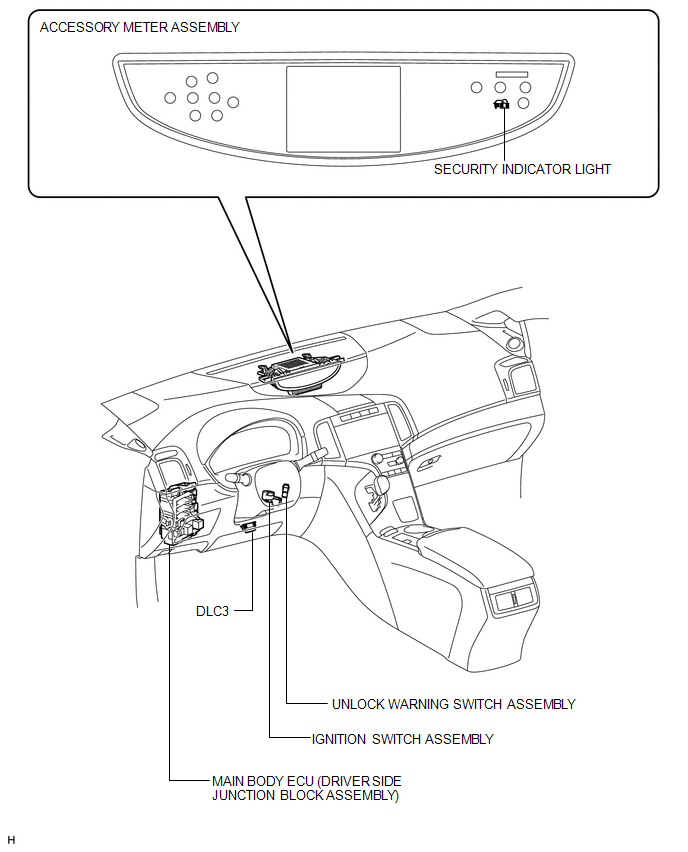
PARTS LOCATION
ILLUSTRATION
.png)
ILLUSTRATION
ILLUSTRATION
.png)
 Precaution
PRECAUTION
1. NOTICE FOR INITIALIZATION
NOTICE:
When disconnecting the cable from the negative (-) battery terminal, initialize
the following system after the cable is reconnected.
Sy ...
 System Description
SYSTEM DESCRIPTION
1. OUTLINE OF THEFT DETERRENT SYSTEM
The theft deterrent system can be set by locking the doors using the
transmitter or key, or by opening and closing the doors (for d ...
Other materials about Toyota Venza:
Garage Door Opener Switch
Components
COMPONENTS
ILLUSTRATION
Removal
REMOVAL
PROCEDURE
1. REMOVE ROOF CONSOLE BOX ASSEMBLY (GARAGE DOOR OPENER SWITCH)
(a) Using a moulding remover, disengage the 2 claws and 2 clips.
Text in Illustration
*1 ...
Customize Parameters
CUSTOMIZE PARAMETERS
1. INTUITIVE PARKING ASSIST SYSTEM (See page
)
2. POWER DOOR LOCK CONTROL SYSTEM (See page
)
3. WIRELESS DOOR LOCK CONTROL SYSTEM (w/ Smart Key System) (See page
)
4. WIRELESS DOOR LOCK CONTROL SYSTEM (w/o Smart Key System) (Se ...
System Description
SYSTEM DESCRIPTION
1. ENGINE IMMOBILISER SYSTEM DESCRIPTION
The engine immobiliser system is designed to prevent the vehicle from being stolen.
This system uses the transponder key ECU assembly that stores the key codes of authorized
ignition keys. If an ...

0.1243