Toyota Venza: Parts Location
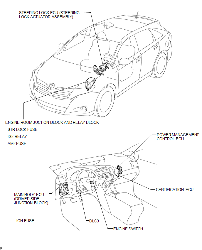
PARTS LOCATION
ILLUSTRATION
 Precaution
PRECAUTION
1. NOTICE FOR INITIALIZATION:
NOTICE:
When disconnecting the cable from the negative (-) battery terminal, initialize
the following systems after the cable is reconnected.
...
 System Description
SYSTEM DESCRIPTION
1. DESCRIPTION
(a) The steering lock system locks/unlocks the steering when by activating the
steering lock bar with a motor. The steering lock ECU (steering lock actuator assem ...
Other materials about Toyota Venza:
Bleeding
BLEEDING
CAUTION / NOTICE / HINT
NOTICE:
Do not allow brake fluid to adhere to any painted surface such as the
vehicle body. If brake fluid leaks onto any painted surface, immediately
wash it off.
Before bleeding the brake system, confir ...
Removal
REMOVAL
PROCEDURE
1. REMOVE NO. 1 ENGINE UNDER COVER
2. REMOVE NO. 2 ENGINE UNDER COVER
3. REMOVE WINDSHIELD WIPER MOTOR AND LINK
(a) Remove the windshield wiper motor and link (See page
).
4. REMOVE OUTER COWL TOP PANEL SUB-ASSEMBLY
5. DRAIN ENGIN ...
Antenna Coil Open / Short (B2784)
DESCRIPTION
This DTC is stored when there is an open or short in the transponder key coil
(built into the engine switch).
DTC No.
DTC Detection Condition
Trouble Area
B2784
Transponder key coil i ...

0.1633