Toyota Venza: Components
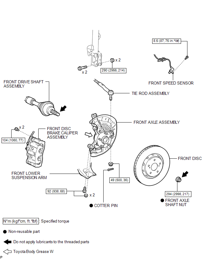
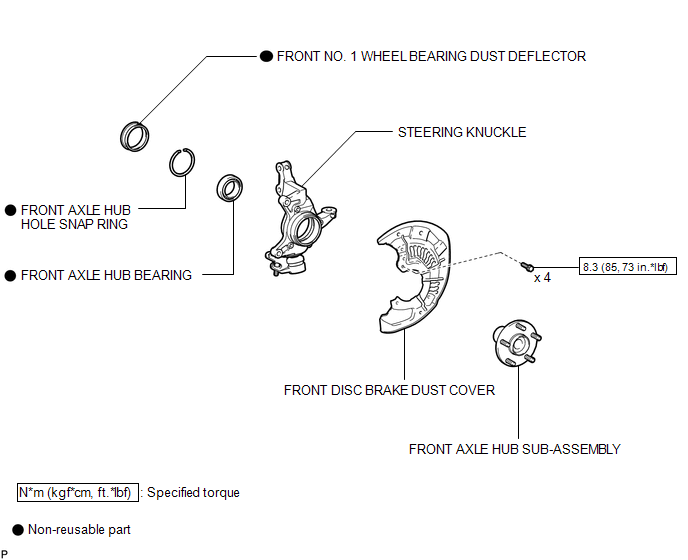
COMPONENTS
ILLUSTRATION
ILLUSTRATION
 Front Axle Hub
...
 On-vehicle Inspection
ON-VEHICLE INSPECTION
CAUTION / NOTICE / HINT
HINT:
Use the same procedure for the RH side and LH side.
The procedure listed below is for the LH side.
PROCEDURE
1. REMOVE FRONT ...
Other materials about Toyota Venza:
Diagnostic Trouble Code Chart
DIAGNOSTIC TROUBLE CODE CHART
HINT:
If a trouble code is output during the DTC check, inspect the trouble areas listed
for that code. For details of the code, refer to "See page" in the DTC chart.
Inspect the fuses and relays before troub ...
Moon roof
Use the overhead switches to open, close, and tilt the moon roof up and down.
- Opening and closing
1. Open
The moon roof stops slightly before the fully open position to reduce wind noise.
Move the switch backward again to fully open.
2. Close ( ...
Engine Coolant Temperature / Intake Air Temperature Correlation (P011B)
DESCRIPTION
The engine has two temperature sensors, an engine coolant temperature sensor
and an intake air temperature sensor, to detect the temperature while the engine
is in operation. A thermistor, whose resistance value varies according to the tempera ...

0.1295