Toyota Venza: Navigation Antenna
Components
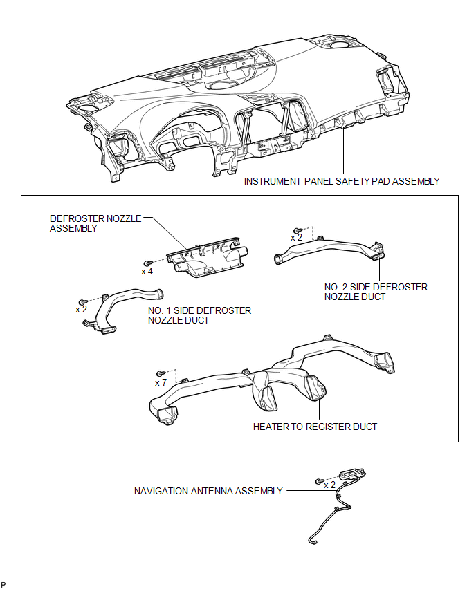
COMPONENTS
ILLUSTRATION
Removal
REMOVAL
PROCEDURE
1. REMOVE INSTRUMENT PANEL SAFETY PAD ASSEMBLY
HINT:
Refer to the procedure up to Remove Instrument Panel Safety Pad Assembly (See
page .gif) ).
).
2. REMOVE NO. 1 SIDE DEFROSTER NOZZLE DUCT
3. REMOVE NO. 2 SIDE DEFROSTER NOZZLE DUCT
4. REMOVE DEFROSTER NOZZLE ASSEMBLY
5. REMOVE HEATER TO REGISTER DUCT
6. REMOVE NAVIGATION ANTENNA ASSEMBLY
|
(a) Disengage the 4 clamps. |
|
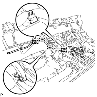
(b) Remove the 2 screws and the navigation antenna assembly.
Installation
INSTALLATION
PROCEDURE
1. INSTALL NAVIGATION ANTENNA ASSEMBLY
|
(a) Install the navigation antenna assembly with the 2 screws. |
|
.png)
(b) Engage the 4 clamps.
2. INSTALL HEATER TO REGISTER DUCT
.gif)
3. INSTALL DEFROSTER NOZZLE ASSEMBLY
4. INSTALL NO. 2 SIDE DEFROSTER NOZZLE DUCT
5. INSTALL NO. 1 SIDE DEFROSTER NOZZLE DUCT
6. INSTALL INSTRUMENT PANEL SAFETY PAD ASSEMBLY
HINT:
Refer to the procedure from Install Roof Headlining Assembly (See page
).


Other materials about Toyota Venza:
Wireless Transmitter Memory Function does not Operate
DESCRIPTION
Key IDs can be registered (linked) with either the M1 or M2 seat memory switches.
The key ID registration procedure should be performed while the electrical key transmitter
sub-assembly or door control transmitter assembly is in the vehicle, t ...
Problem Symptoms Table
PROBLEM SYMPTOMS TABLE
HINT:
Use the table below to help determine the cause of problem symptoms.
If multiple suspected areas are listed, the potential causes of the symptoms
are listed in order of probability in the "Suspected Area" ...
Dinghy towing
Your vehicle is not designed to be dinghy towed (with four wheels on the ground)
behind a motor home.
NOTICE
- To avoid serious damage to your vehicle
Do not tow your vehicle with four wheels on the ground.
- To prevent causing serious dama ...

0.1181