Toyota Venza: Installation
INSTALLATION
PROCEDURE
1. INSTALL CHECK VALVE GROMMET
(a) Install a new check valve grommet to the brake booster assembly.
2. INSTALL BRAKE VACUUM CHECK VALVE ASSEMBLY
(a) Install the brake vacuum check valve assembly to the brake booster assembly.
3. INSTALL BRAKE MASTER CYLINDER PUSH ROD CLEVIS
(a) Temporarily install the lock nut and brake master cylinder push rod clevis to the brake booster assembly.
|
(b) Set the push rod length as shown in the illustration. Text in Illustration
Standard length*1: 155.1 to 156.1 mm (6.11 to 6.15 in.) |
|
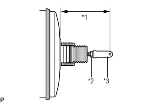
(c) Tighten the lock nut.
Torque:
26 N·m {265 kgf·cm, 19 ft·lbf}
4. INSTALL BRAKE BOOSTER GASKET
|
(a) Install a new brake booster gasket to the brake booster assembly. |
|
.png)
5. INSTALL BRAKE BOOSTER ASSEMBLY
|
(a) Install the brake booster assembly to the body with the 4 nuts. Torque: 13 N·m {130 kgf·cm, 9 ft·lbf} NOTICE: Do not damage the brake lines. |
|
.png)
6. INSTALL PUSH ROD PIN
|
(a) Apply lithium soap base glycol grease to the push rod pin. |
|
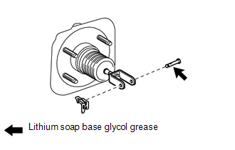
(b) Connect the brake master cylinder push rod clevis to the brake pedal sub-assembly, and install the push rod pin and a new clip as shown in the illustration.
7. INSTALL NO. 1 VACUUM HOSE CONNECTOR (for 1AR-FE)
|
(a) Install the No. 1 vacuum hose connector with the 2 nuts. Torque: 5.4 N·m {55 kgf·cm, 48 in·lbf} |
|
.png)
(b) Connect the vacuum hose to the brake booster assembly, and slide the clip to secure the vacuum hose.
8. CONNECT VACUUM HOSE (for 2GR-FE)
|
(a) Connect the vacuum hose to the brake booster assembly, and slide the clip to secure the vacuum hose. |
|
.png)
9. INSTALL BRAKE MASTER CYLINDER SUB-ASSEMBLY
.gif)
10. FILL RESERVOIR WITH BRAKE FLUID
11. BLEED BRAKE MASTER CYLINDER
12. BLEED BRAKE LINE
13. INSPECT FOR BRAKE FLUID LEAK
14. INSPECT FLUID LEVEL IN RESERVOIR
15. INSPECT AND ADJUST BRAKE PEDAL
HINT:
See page
16. INSTALL SECURITY HORN ASSEMBLY (w/ Security Horn)
17. INSTALL AIR CLEANER CASE (for 1AR-FE)
18. INSTALL AIR CLEANER CASE (for 2GR-FE)
19. INSTALL AIR CLEANER FILTER ELEMENT SUB-ASSEMBLY
20. INSTALL AIR CLEANER CAP SUB-ASSEMBLY (for 1AR-FE)
21. INSTALL AIR CLEANER CAP SUB-ASSEMBLY (for 2GR-FE)
22. INSTALL OUTER COWL TOP PANEL
23. INSTALL WINDSHIELD WIPER MOTOR AND LINK ASSEMBLY
24. INSTALL COWL TOP VENTILATOR LOUVER SUB-ASSEMBLY
25. INSTALL FRONT FENDER TO COWL SIDE SEAL RH
26. INSTALL FRONT FENDER TO COWL SIDE SEAL LH
27. INSTALL FRONT WIPER ARM AND BLADE ASSEMBLY RH
28. INSTALL FRONT WIPER ARM AND BLADE ASSEMBLY LH
29. INSTALL FRONT WIPER ARM HEAD CAP
 Inspection
INSPECTION
PROCEDURE
1. INSPECT BRAKE VACUUM CHECK VALVE ASSEMBLY
(a) Check that there is ventilation from the booster to the engine, and
no ventilation from the engine to the booste ...
 Brake Fluid
...
Other materials about Toyota Venza:
Fail-safe Chart
FAIL-SAFE CHART
If any of the following DTCs are stored, the ECM enters fail-safe mode to allow
the vehicle to be driven temporarily or stops fuel injection.
DTC Code
Component
Fail-Safe Operation
Fail-Safe Deact ...
Front Door Courtesy Switch
Components
COMPONENTS
ILLUSTRATION
Inspection
INSPECTION
PROCEDURE
1. INSPECT COURTESY LIGHT SWITCH
(a) Measure the resistance according to the value(s) in the table below.
Standard Resistance:
Tester Connection
Switch C ...
Trip information
Display items can be switched by pressing the “INFO” button.
- Average Fuel Economy
Displays the average fuel consumption since the function was reset.
• The function can be reset by pressing and holding the “SELECT RESET” button
when the ...

0.1411