Toyota Venza: Installation
INSTALLATION
PROCEDURE
1. INSTALL FRONT BUMPER ASSEMBLY
(a) Connect each connector.
|
(b) Engage the 4 claws to install the front bumper assembly. HINT: Use the same procedure for the RH side and LH side. |
|
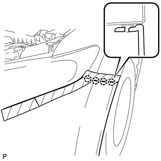
(c) Install the clip.
(d) Install the 2 bolts and 8 screws.
|
(e) Install the 2 pin hold clips. Text in Illustration
NOTICE: Insert the pin hold clip with the slot aligned vertically. Do not rotate the clip after inserting it. After installation, confirm that the slot is vertical. HINT: Use the same procedure for the RH side and LH side. |
|
2. INSTALL RADIATOR GRILLE
.gif)
3. INSTALL COOL AIR INTAKE DUCT SEAL
(a) Install the cool air intake duct seal with the 12 clips.
4. ADJUST FOG LIGHT ASSEMBLY
(See page )
 Reassembly
REASSEMBLY
PROCEDURE
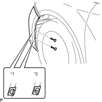
1. INSTALL FRONT BUMPER SIDE RETAINER LH
(a) Engage the claw and install the front bumper side retainer LH.
Text in Illustration
*1
...

Other materials about Toyota Venza:
Engine compartment
► 2GR-FE engine
1. Engine coolant reservoir
2. Engine oil filler cap
3. Engine oil level dipstick
4. Brake fluid reservoir
5. Battery
6. Fuse box
7. Electric cooling fans
8. Condenser
9. Radiator
10.Washer fluid tank
► 1AR-FE engine
...
Transmission Fluid Pressure Sensor / Switch "E" Circuit Low (P0989,P0990)
DESCRIPTION
ATF pressure switch No. 3 is installed in the lock-up solenoid ATF output passage
and is used to detect a malfunction in the lock-up solenoid.
DTC No.
DTC Detection Condition
Trouble Area
P0989
...
On-vehicle Inspection
ON-VEHICLE INSPECTION
PROCEDURE
1. CHECK FOR FUEL PUMP OPERATION AND INSPECT FOR FUEL LEAK
(a) Check fuel pump operation.
(1) Connect the Techstream to the DLC3.
(2) Turn the ignition switch to ON and turn the Techstream on.
NOTICE:
Do not start the eng ...

0.1558