Toyota Venza: Horn
Components
COMPONENTS
ILLUSTRATION
Inspection
INSPECTION
PROCEDURE
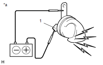
1. INSPECT LOW PITCHED HORN ASSEMBLY
|
(a) Apply battery voltage and check the operation of the low pitched horn assembly according to the table below. OK:
If the result is not as specified, replace the low pitched horn assembly. |
|
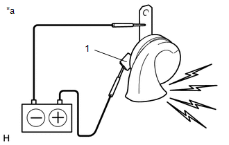
2. INSPECT HIGH PITCHED HORN ASSEMBLY
|
(a) Apply battery voltage and check the operation of the high pitched horn assembly according to the table below. OK:
If the result is not as specified, replace the high pitched horn assembly. |
|
Removal
REMOVAL
PROCEDURE
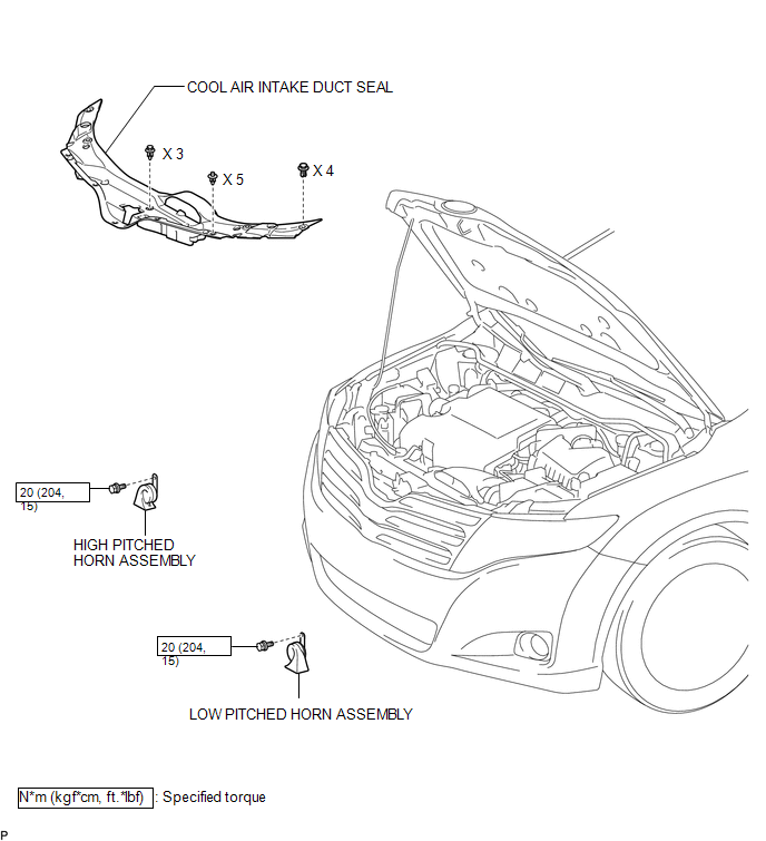
1. REMOVE COOL AIR INTAKE DUCT SEAL
.gif)
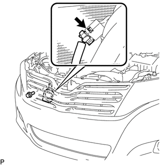
2. REMOVE LOW PITCHED HORN ASSEMBLY
|
(a) Disconnect the connector. |
|
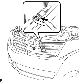
(b) Remove the bolt and low pitched horn assembly.
3. REMOVE HIGH PITCHED HORN ASSEMBLY
|
(a) Disconnect the connector. |
|
(b) Remove the bolt and high pitched horn assembly.
Installation
INSTALLATION
PROCEDURE
1. INSTALL LOW PITCHED HORN ASSEMBLY
(a) Install the low pitched horn assembly with the bolt.
Torque:
20 N·m {204 kgf·cm, 15 ft·lbf}
(b) Connect the connector.
2. INSTALL HIGH PITCHED HORN ASSEMBLY
(a) Install the high pitched horn assembly with the bolt.
Torque:
20 N·m {204 kgf·cm, 15 ft·lbf}
(b) Connect the connector.
3. INSTALL COOL AIR INTAKE DUCT SEAL
.gif)
 Horn
Horn
...
 Horn System
Precaution
PRECAUTION
NOTICE:
When disconnecting the cable from the negative (-) battery terminal, initialize
the following system after the cable is reconnected.
System Name
...
Other materials about Toyota Venza:
Portable Player cannot be Registered
CAUTION / NOTICE / HINT
HINT:
Some versions of "Bluetooth" compatible audio players may not function properly,
or the functions may be limited using the navigation receiver assembly, even if
the portable audio player itself can play files (See ...
Terminals Of Ecu
TERMINALS OF ECU
1. CHECK POWER BACK DOOR ECU (POWER BACK DOOR MOTOR UNIT) (w/ POWER BACK DOOR
SYSTEM)
(a) Disconnect the L20 power back door ECU connector.
(b) Measure the voltage and resistance according to the value(s) in the table
below.
...
Short in GPS Antenna (B15C0,B15C1)
DESCRIPTION
These DTCs are stored when a malfunction occurs in the navigation antenna assembly.
DTC No.
DTC Detection Condition
Trouble Area
B15C0
Navigation antenna malfunction
...

0.127