Toyota Venza: Garage Door Opener Switch
Components
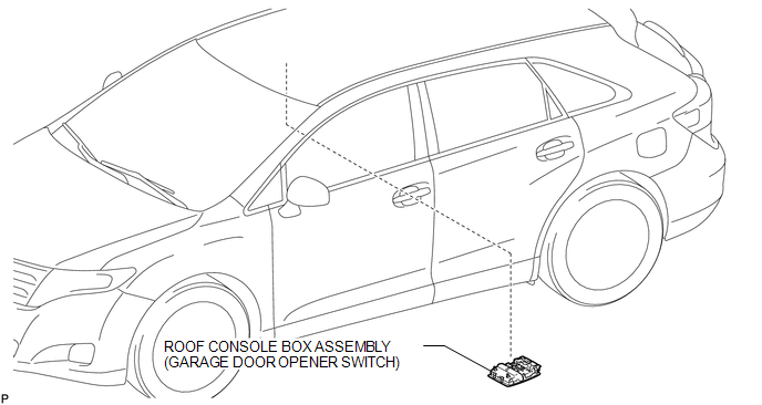
COMPONENTS
ILLUSTRATION
Removal
REMOVAL
PROCEDURE
1. REMOVE ROOF CONSOLE BOX ASSEMBLY (GARAGE DOOR OPENER SWITCH)
|
(a) Using a moulding remover, disengage the 2 claws and 2 clips. Text in Illustration
|
|
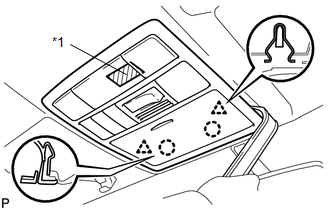
(b) Disengage the fastener and remove the roof console box assembly (garage door opener switch).
Installation
INSTALLATION
PROCEDURE
1. INSTALL ROOF CONSOLE BOX ASSEMBLY (GARAGE DOOR OPENER SWITCH)
|
(a) Engage the fastener. Text in Illustration
|
|
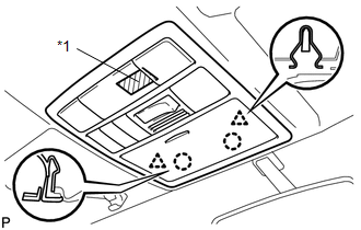
(b) Engage the 2 claws and 2 clips, and install the roof console box assembly (garage door opener switch).


Other materials about Toyota Venza:
Inspection
INSPECTION
PROCEDURE
1. INSPECT TRANSMISSION OIL CLEANER MAGNET
(a) Use the removed transmission oil cleaner magnets to collect any steel
chips. Examine the chips and particles in the automatic transaxle oil pan
sub-assembly and on the tr ...
ECU Power Source Circuit
DESCRIPTION
This circuit provides power to operate the transponder key ECU assembly.
WIRING DIAGRAM
CAUTION / NOTICE / HINT
NOTICE:
If the transponder key ECU assembly is replaced, register the key and ECU communication
ID (See page ).
PROCEDURE
...
Satellite Radio Broadcast cannot be Received
CAUTION / NOTICE / HINT
NOTICE:
Some satellite radio broadcasts require payment. A contract must be made between
a satellite radio company and the user. If the contract expires, it will not be
possible to listen to the broadcast.
PROCEDURE
1 ...

0.1153