Toyota Venza: Components
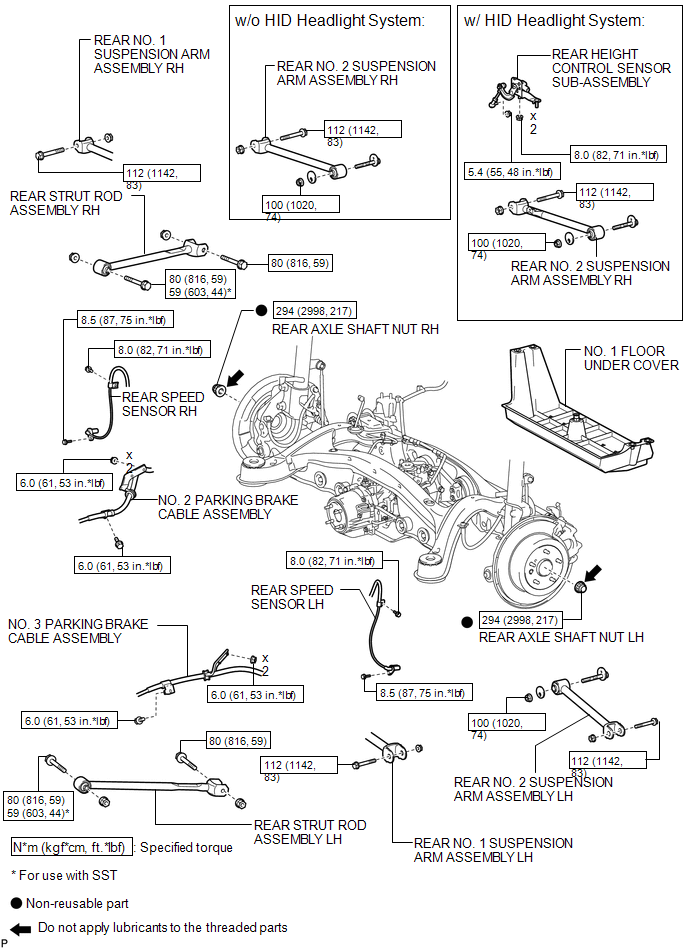
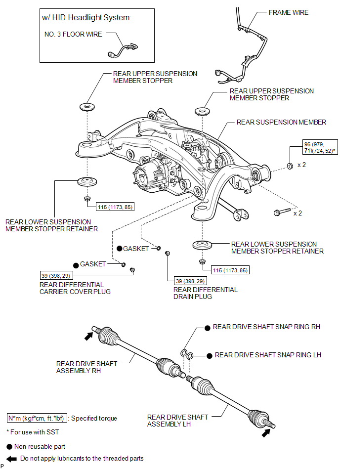
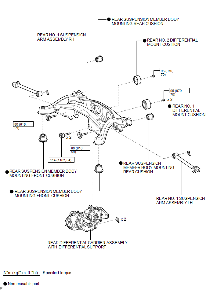
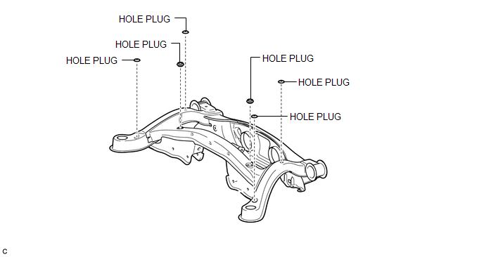
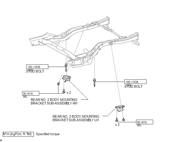
COMPONENTS
ILLUSTRATION
.png)
ILLUSTRATION
ILLUSTRATION
ILLUSTRATION
ILLUSTRATION
ILLUSTRATION

 Removal
REMOVAL
PROCEDURE
1. REMOVE REAR WHEELS
2. REMOVE CENTER EXHAUST PIPE ASSEMBLY
(a) Remove the center exhaust pipe assembly.
HINT:
Refer to the instructions for Removal of the exhaust pipe (See p ...
Other materials about Toyota Venza:
How To Proceed With Troubleshooting
PROCEDURE
1.
CHECK TIRE AND WHEEL SYSTEM
DIAGNOSIS OF IRREGULAR TIRE WEAR
GO TO STEP 11
DIAGNOSIS OF TIRE VIBRATION
2.
...
Installation
INSTALLATION
CAUTION / NOTICE / HINT
HINT:
Perform "Inspection After Repair" after replacing the engine assembly (See page
).
PROCEDURE
1. INSTALL IGNITION COIL ASSEMBLY
2. INSTALL FUEL DELIVERY PIPE SUB-ASSEMBLY
3. INSTALL ENGINE COOL ...
Customize Parameters
CUSTOMIZE PARAMETERS
1. CUSTOMIZING FUNCTION WITH TECHSTREAM
HINT:
The items in the table below can be customized.
NOTICE:
When the customer requests a change in a function, first make sure that
the function can be customized.
Be sure to m ...

0.1451