Toyota Venza: Exterior
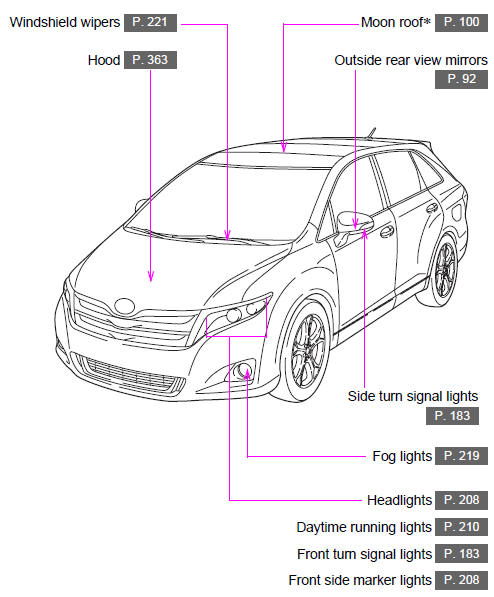
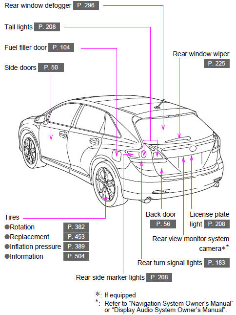
 Pictorial index
...
 Interior
...
Other materials about Toyota Venza:
Headlight switch
The headlights can be operated manually or automatically.
Turning the end of the lever turns on the lights as follows.
Type A
The daytime running lights turn
on.
The headlights, parking lights, daytime running lights and so on turn on and
off auto ...
Seat Heater Switch
Components
COMPONENTS
ILLUSTRATION
Removal
REMOVAL
PROCEDURE
1. REMOVE UPPER CONSOLE PANEL SUB-ASSEMBLY
2. REMOVE SEAT HEATER SWITCH
(a) Disengage the 2 claws and remove the seat heater switch as shown
in the illustration.
...
Installation
INSTALLATION
CAUTION / NOTICE / HINT
HINT:
Use the same procedure for the RH side and LH side.
The procedure listed below is for the LH side.
PROCEDURE
1. INSTALL FRONT AXLE HUB BEARING
(a) Using SST and a press, install a ne ...

0.1449