Toyota Venza: Engine Oil Cooler
Components
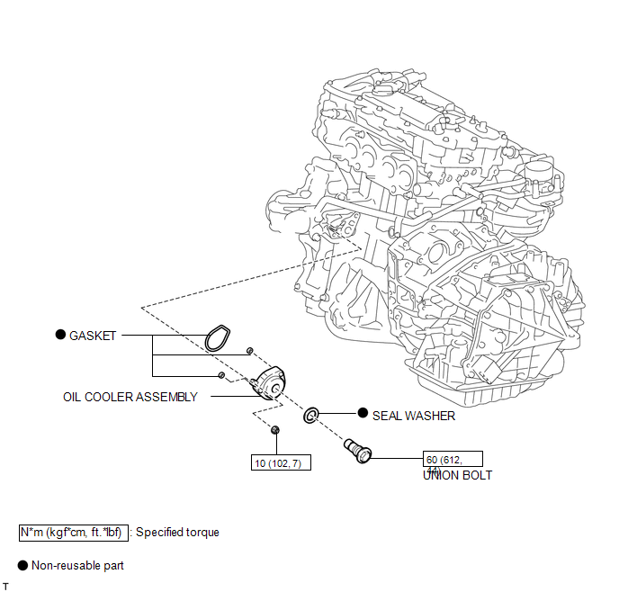
COMPONENTS
ILLUSTRATION
Removal
REMOVAL
PROCEDURE
1. REMOVE EXHAUST MANIFOLD ASSEMBLY
HINT:
See page .gif)
2. DRAIN ENGINE OIL
3. DRAIN ENGINE COOLANT
4. REMOVE OIL COOLER ASSEMBLY
|
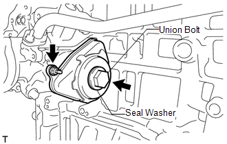
(a) Remove the nut, union bolt, seal washer and oil cooler assembly. |
|
(b) Remove the 3 gaskets from the oil cooler assembly.
Inspection
INSPECTION
PROCEDURE
1. INSPECT ENGINE OIL COOLER
(a) Visually check the engine oil cooler for cracks or damage.
If cracks or damage are found, replace the engine oil cooler.
Installation
INSTALLATION
PROCEDURE
1. INSTALL OIL COOLER ASSEMBLY
(a) Clean the oil cooler contact surface on the cooler mounting.
(b) Apply a light coat of engine oil to 3 new gaskets.
(c) Install the 3 new gaskets to the oil cooler assembly.
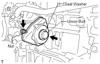
(d) Temporarily install the oil cooler assembly with the union bolt, nut and a new seal washer.
|
(e) Tighten the bolt and nut in several steps, in the sequence shown in the illustration. Torque: Union Bolt : 60 N·m {612 kgf·cm, 44 ft·lbf} Nut : 10 N·m {102 kgf·cm, 7 ft·lbf} |
|
2. INSTALL EXHAUST MANIFOLD ASSEMBLY
HINT:
See page .gif)
3. ADD ENGINE OIL
4. ADD ENGINE COOLANT
5. INSPECT FOR OIL LEAK
6. INSPECT ENGINE OIL LEVEL

 Lubrication System
On-vehicle Inspection
ON-VEHICLE INSPECTION
PROCEDURE
1. INSPECT ENGINE OIL LEVEL
(a) Warm up the engine, stop it and wait 5 minutes. The engine oil level should
be between the low level mark ...
Other materials about Toyota Venza:
Inspection
INSPECTION
PROCEDURE
1. INSPECT TRANSMISSION OIL CLEANER MAGNET
(a) Use the removed transmission oil cleaner magnets to collect any steel
chips. Examine the chips and particles in the automatic transaxle oil pan
sub-assembly and on the tr ...
Unlock Position Sensor Signal Circuit
DESCRIPTION
The unlock position sensor is one of the components comprising the steering lock
ECU (steering lock actuator assembly). The sensor switch contact closes when the
steering lock is released. The steering lock release signal is then sent to the
...
Disassembly
DISASSEMBLY
PROCEDURE
1. REMOVE HOOD TO RADIATOR SUPPORT SEAL
(a) Using a clip remover, disengage the 10 clips and remove the hood
to radiator support seal.
2. REMOVE HOOD INSULATOR
...

0.1378