Toyota Venza: Components
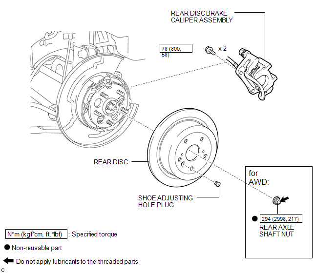
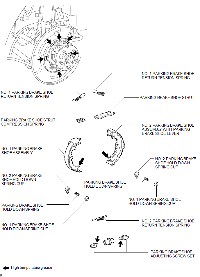
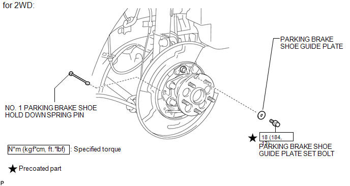
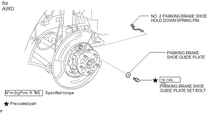
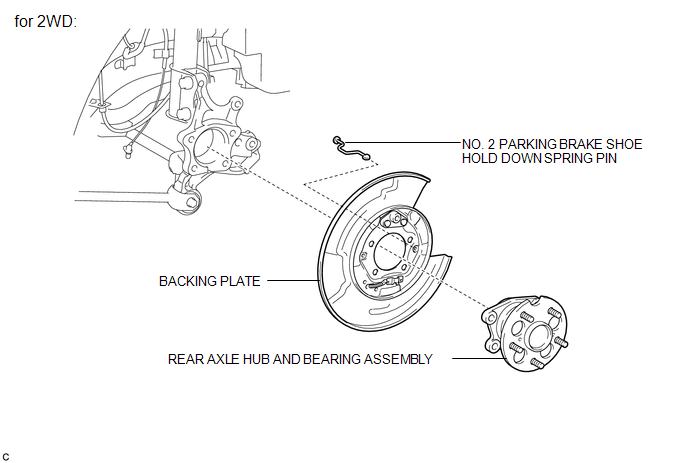
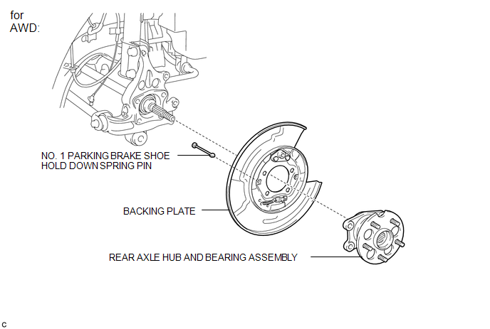
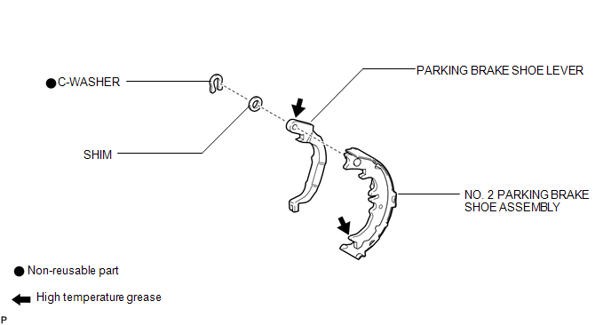
COMPONENTS
ILLUSTRATION
ILLUSTRATION
ILLUSTRATION
ILLUSTRATION
ILLUSTRATION
ILLUSTRATION
ILLUSTRATION

 Disassembly
DISASSEMBLY
CAUTION / NOTICE / HINT
HINT:
Use the same procedure for the RH side and the LH side.
The procedure listed below is for the LH side.
PROCEDURE
1. REMOVE REAR WHEEL
...
Other materials about Toyota Venza:
Open or Short Circuit in ABS Motor Relay Circuit (C0273/13)
DESCRIPTION
The ABS motor relay supplies power to the ABS pump motor. While the ABS is activated,
the ECU turns the motor relay on and operates the ABS pump motor.
If the voltage supplied to the motor relay (+BM) is below the DTCs detection
threshold due ...
Problem Symptoms Table
PROBLEM SYMPTOMS TABLE
HINT:
Use the table below to help determine the cause of problem symptoms. If multiple
suspected areas are listed, the potential causes of the symptoms are listed in order
of probability in the "Suspected Area" column of ...
Electrical Key Oscillator(for Center Floor)
Components
COMPONENTS
ILLUSTRATION
Installation
INSTALLATION
PROCEDURE
1. INSTALL ELECTRICAL KEY OSCILLATOR
(a) Engage the clamp and install the electrical key oscillator.
NOTICE:
Be careful when installing the electrical key osci ...

0.1516