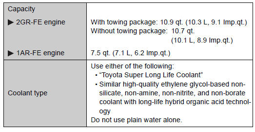
Toyota Venza: Cooling system
 Lubrication system
- Engine oil selection
“Toyota Genuine Motor Oil” is used in your Toyota vehicle. Use Toyota approved
“Toyota Genuine Motor Oil” or equivalent to satisfy the following grade and vis ...
 Ignition system
NOTICE - Iridium-tipped spark plugs Use only iridium-tipped spark plugs.
Do not adjust gap when tuning engine. ...
Other materials about Toyota Venza:
Diagnostic Trouble Code Chart
DIAGNOSTIC TROUBLE CODE CHART
HINT:
Parameters listed in the chart may not be exactly the same as your readings due
to the type of instrument or other factors. If a trouble code is displayed during
the DTC check, inspect the trouble areas listed for that ...
Front seats
► Power seat
1. Seat position fore/aft control switch
2. Seatback angle control switch
3. Seat cushion (front) angle control switch (driver’s side only)
4. Vertical height control switch (driver’s side only)
5. Lumbar support control switch
& ...
Disassembly
DISASSEMBLY
PROCEDURE
1. REMOVE SEAT ADJUSTER COVER CAP
(a) Remove the seat adjuster cover cap.
HINT:
Use the same procedure for the RH side and LH side.
2. REMOVE RECLINING POWER SEAT SWITCH ...

0.1558