Toyota Venza: Components
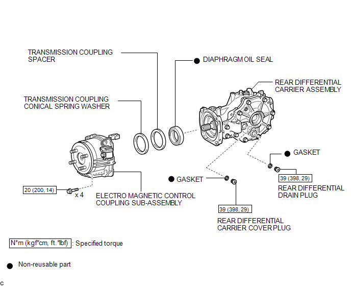
COMPONENTS
ILLUSTRATION
.png)
ILLUSTRATION

 Replacement
REPLACEMENT
PROCEDURE
1. REMOVE CENTER EXHAUST PIPE ASSEMBLY
(a) Remove the center exhaust pipe assembly.
HINT:
Refer to the instructions for Removal of the exhaust pipe (See page
for 2GR-FE, ...
Other materials about Toyota Venza:
Removal
REMOVAL
PROCEDURE
1. REMOVE AIR CONDITIONING UNIT ASSEMBLY
(See page )
2. REMOVE NO. 1 FINISH PANEL MOUNTING BRACKET
3. REMOVE NO. 2 FINISH PANEL MOUNTING BRACKET
4. REMOVE NO. 3 AIR DUCT SUB-ASSEMBLY
5. REMOVE NO. 2 AIR DUCT SUB-ASSEMBLY
...
Utility vehicle feature
• Specific design characteristics give it a higher center of gravity than ordinary
passenger cars. This vehicle design feature causes this type of vehicle to be more
likely to rollover. And, utility vehicles have a significantly higher rollover rate
th ...
Removal
REMOVAL
PROCEDURE
1. REMOVE REAR SEAT HEADREST ASSEMBLY
(a) Press the headrest support button and pull up the rear seat headrest
assembly as shown in the illustration.
2. REMOVE REAR SEAT CENTER ...

0.176