Toyota Venza: Components
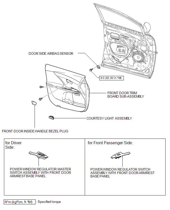
COMPONENTS
ILLUSTRATION

 On-vehicle Inspection
ON-VEHICLE INSPECTION
CAUTION / NOTICE / HINT
CAUTION:
Be sure to follow the correct removal and installation procedures of the door
side airbag sensor.
PROCEDURE
1. INSPECT DOOR SIDE AIRBAG SE ...
Other materials about Toyota Venza:
Removal
REMOVAL
PROCEDURE
1. DISCONNECT CABLE FROM NEGATIVE BATTERY TERMINAL
CAUTION:
Wait at least 90 seconds after disconnecting the cable from the negative (-)
battery terminal to disable the SRS system (See page
).
NOTICE:
When disconnecting the cable, s ...
Terminals Of Ecu
TERMINALS OF ECU
NOTICE:
Turn the ignition switch off before measuring the resistances between
CAN bus main wires and between CAN bus branch wires.
Turn the ignition switch off before inspecting CAN bus wires for a ground
short.
After ...
Security Indicator Light Circuit
DESCRIPTION
The security indicator light blinks continuously due to a continuous signal received
from the transponder key ECU assembly while in the armed state.
WIRING DIAGRAM
CAUTION / NOTICE / HINT
NOTICE:
If the transponder key ECU assembly is repl ...

0.1547