Toyota Venza: Components
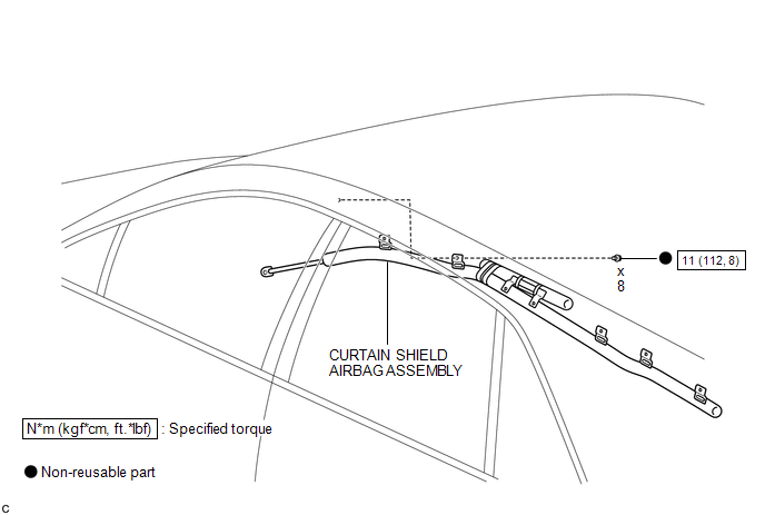
COMPONENTS
ILLUSTRATION

 On-vehicle Inspection
ON-VEHICLE INSPECTION
CAUTION / NOTICE / HINT
CAUTION:
Be sure to follow the correct removal and installation procedures of the curtain
shield airbag assembly.
PROCEDURE
1. INSPECT CURTAIN SHIE ...
Other materials about Toyota Venza:
Trip information
Display items can be switched by pressing the “INFO” button.
- Average Fuel Economy
Displays the average fuel consumption since the function was reset.
• The function can be reset by pressing and holding the “SELECT RESET” button
when the ...
Indicators and warning lights
The indicator and warning lights on the instrument cluster and center panel
inform the driver of the status of the vehicle’s various systems.
For the purpose of explanation, the following illustration displays all indicators
and warning lights illuminat ...
Removal
REMOVAL
PROCEDURE
1. DISCONNECT CABLE FROM NEGATIVE BATTERY TERMINAL
CAUTION:
Wait at least 90 seconds after disconnecting the cable from the negative (-)
battery terminal to disable the SRS system (See page
).
NOTICE:
When disconnecting the cable, s ...

0.1598