Toyota Venza: Components
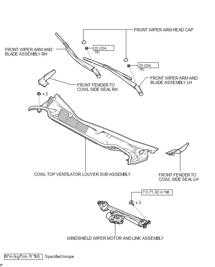
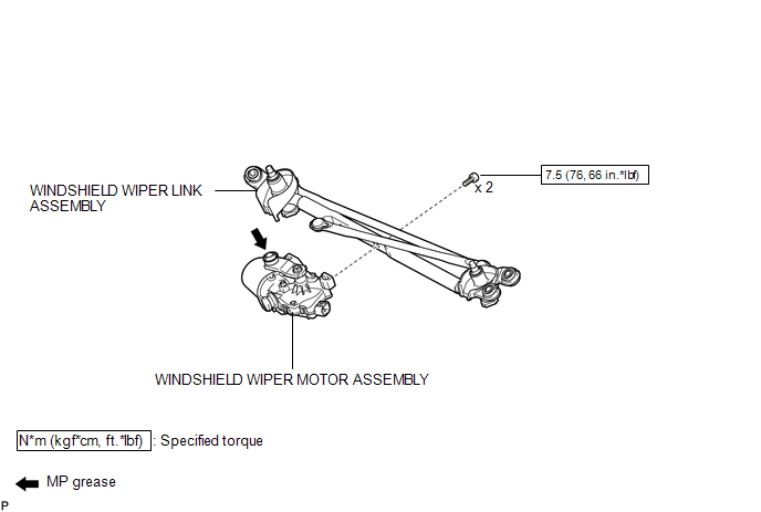
COMPONENTS
ILLUSTRATION
ILLUSTRATION

 On-vehicle Inspection
ON-VEHICLE INSPECTION
PROCEDURE
1. INSPECT WINDSHIELD WIPER MOTOR ASSEMBLY
(a) for RH Side
(1) Operate the windshield wiper motor assembly.
...
Other materials about Toyota Venza:
Diagnostic Trouble Code Chart
DIAGNOSTIC TROUBLE CODE CHART
Lighting System
DTC Code
Detection Item
See page
B1244
Light Sensor Circuit Malfunction
B124D
Lost Communication with AFS LIN
...
Precaution
PRECAUTION
1. PRECAUTION FOR DISCONNECTING CABLE FROM NEGATIVE BATTERY TERMINAL
NOTICE:
After the ignition switch is turned off, the radio and display receiver
assembly records various types of memory and settings. As a result, after
turning ...
Ultrasonic Sensor(for Front Side)
Components
COMPONENTS
ILLUSTRATION
Removal
REMOVAL
PROCEDURE
1. REMOVE FRONT BUMPER ASSEMBLY
(See page )
2. REMOVE NO. 1 ULTRASONIC SENSOR
(a) Disengage the 2 claws to remove the No. 1 ultrasonic sensor.
HINT:
Use the same proc ...

0.1217