Toyota Venza: Components
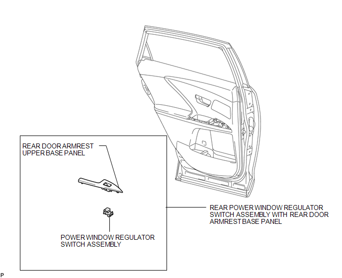
COMPONENTS
ILLUSTRATION

 Inspection
INSPECTION
PROCEDURE
1. INSPECT POWER WINDOW REGULATOR SWITCH ASSEMBLY (for Rear LH)
(a) Check the switch function.
(1) Measure the resistance according to the value(s) in the table b ...
Other materials about Toyota Venza:
Problem Symptoms Table
PROBLEM SYMPTOMS TABLE
HINT:
Use the table below to help determine the cause of problem symptoms.
If multiple suspected areas are listed, the potential causes of the symptoms
are listed in order of probability in the "Suspected Area" ...
Disassembly
DISASSEMBLY
PROCEDURE
1. REMOVE PROPELLER SHAFT
(a) Place matchmarks on both flanges.
Text in Illustration
*1
Matchmark
(b) Remove the 4 nuts, ...
Inspection
INSPECTION
PROCEDURE
1. INSPECT REAR SHOCK ABSORBER ASSEMBLY
(a) Compress and extend the shock absorber rod 4 or more times.
Standard:
There is no abnormal resistance or sound and operation resistance is
normal.
...

0.1392