Toyota Venza: Components
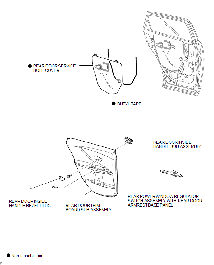
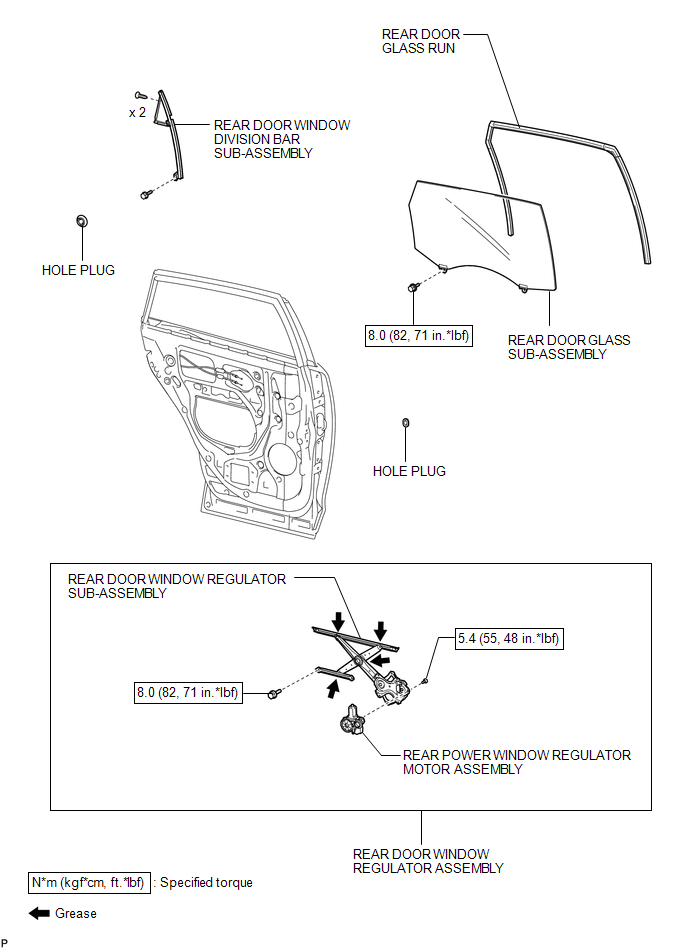
COMPONENTS
ILLUSTRATION
ILLUSTRATION

 Inspection
INSPECTION
PROCEDURE
1. INSPECT REAR POWER WINDOW REGULATOR MOTOR ASSEMBLY LH
(a) Apply positive (+) battery voltage to connector terminal 2 (B).
NOTICE:
Do not apply positive (+) ...
Other materials about Toyota Venza:
Follow the correction procedures. (smart key system)
After taking the specified steps to correct the suspected problem, check that
the warning light turns off.
- If the malfunction indicator lamp comes on while driving
First check the following:
• Is the fuel empty?
If it is, fill the fuel tan ...
System Description
SYSTEM DESCRIPTION
1. POWER WINDOW CONTROL SYSTEM DESCRIPTION
(a) The power window control system controls the power window operation using
the power window regulator motors. The main controls of this system are the power
window regulator master switch a ...
Removal
REMOVAL
CAUTION / NOTICE / HINT
HINT:
Use the same procedure for the RH side and LH side.
The procedure listed below is for the LH side.
PROCEDURE
1. REMOVE FRONT WHEEL
2. REMOVE FRONT AXLE SHAFT NUT
3. SEPARATE FRONT SPEED SENSOR
...

0.1597