Toyota Venza: Components
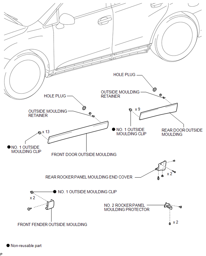
COMPONENTS
ILLUSTRATION
 Side Mudguard
...
 Installation
INSTALLATION
CAUTION / NOTICE / HINT
HINT:
When installing the mouldings, heat the vehicle body and mouldings using a heat
light.
Heating Temperature
Item
Temperature
...
Other materials about Toyota Venza:
Installation
INSTALLATION
PROCEDURE
1. TEMPORARILY TIGHTEN FRONT DISC BRAKE BLEEDER PLUG
(a) Temporarily tighten the front disc brake bleeder plug.
HINT:
Fully tighten the front disc brake bleeder plug after bleeding any air left in
the system.
(b) Install the fron ...
Data Signal Circuit between Radio Receiver and Extension Module
DESCRIPTION
The stereo component tuner assembly sends the image data signal to the radio
and display receiver assembly via this circuit.
WIRING DIAGRAM
PROCEDURE
1.
CHECK NAVIGATION WIRE
(a) Remove the navigation wire ( ...
Adjustment
ADJUSTMENT
CAUTION / NOTICE / HINT
HINT:
Use the same procedure for the RH side and LH side.
The following procedure is for the LH side.
Centering bolts are used to mount the door hinge to the vehicle body
and door. The door cannot b ...

0.1627