Toyota Venza: Components
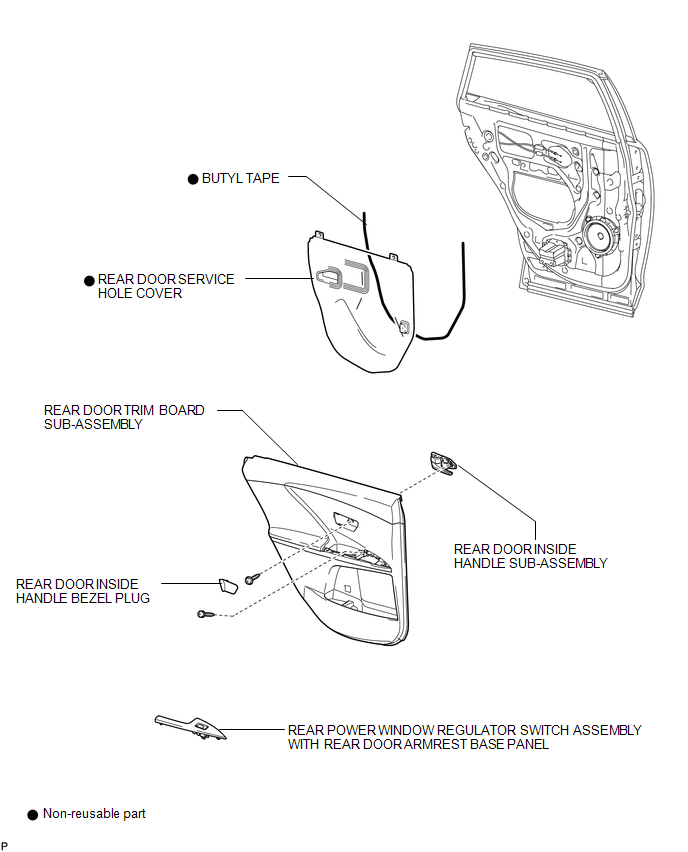
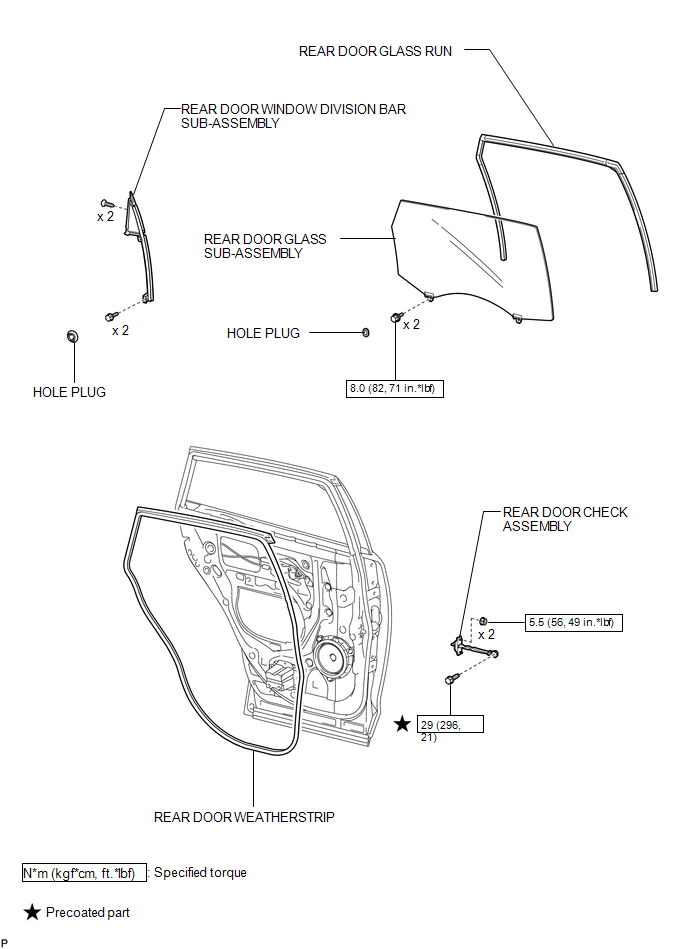
COMPONENTS
ILLUSTRATION
ILLUSTRATION
ILLUSTRATION
.png)

 Removal
REMOVAL
PROCEDURE
1. DISCONNECT CABLE FROM NEGATIVE BATTERY TERMINAL
NOTICE:
When disconnecting the cable, some systems need to be initialized after the cable
is reconnected (See page ).
2. RE ...
Other materials about Toyota Venza:
The distance display and buzzer
When a sensor detects an obstacle, the direction of and the approximate distance
to the obstacle are displayed and the buzzer sounds.
- Corner sensor operation and distance to an obstacle
The system operates when the vehicle approaches within the fol ...
Cleaning and protecting the vehicle exterior
Perform the following to protect the vehicle and maintain it in prime condition.
• Working from top to bottom, liberally apply water to the vehicle body, wheel
wells and underside of the vehicle to remove any dirt and dust.
Wash the vehicle body using a ...
Key battery
Replace the battery with a new one if it is discharged.
- You will need the following items:
• Flathead screwdriver (To prevent damage to the key, cover the tip of the screwdriver
with rag.)
• Small Phillips-head screwdriver
• Lithium battery ...

0.1573