Toyota Venza: Components
COMPONENTS
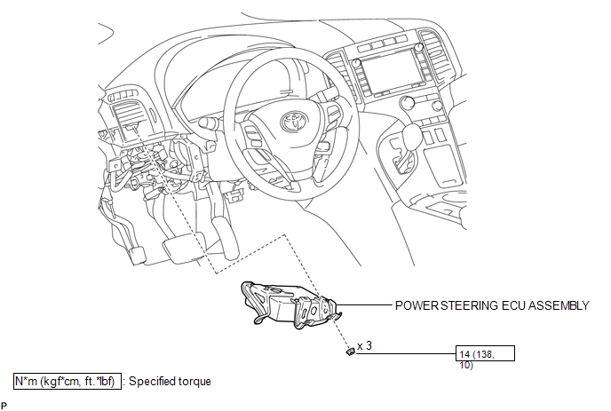
ILLUSTRATION
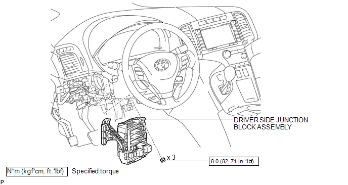
ILLUSTRATION

 Removal
REMOVAL
CAUTION / NOTICE / HINT
CAUTION:
Some of these service operations affect the SRS airbag system. Read the precautionary
notices concerning the SRS airbag system before servicing (See page
...
Other materials about Toyota Venza:
How To Proceed With Troubleshooting
CAUTION / NOTICE / HINT
HINT:
Use the following procedures to troubleshoot the power back door system.
*: Use the Techstream.
PROCEDURE
1.
VEHICLE BROUGHT TO WORKSHOP
NEXT
...
Intake Air Temperature Sensor Gradient Too High (P0111)
DESCRIPTION
The intake air temperature sensor, mounted on the mass air flow meter,
monitors the intake air temperature. The intake air temperature sensor has
a built-in thermistor with a resistance that varies according to the temperature
...
XM Tuner Malfunction (B15BA)
DESCRIPTION
This DTC is stored when a malfunction occurs in the stereo component tuner assembly.
DTC No.
DTC Detection Condition
Trouble Area
B15BA
When either of the following conditions is met:
...

0.1461