Toyota Venza: Components
COMPONENTS
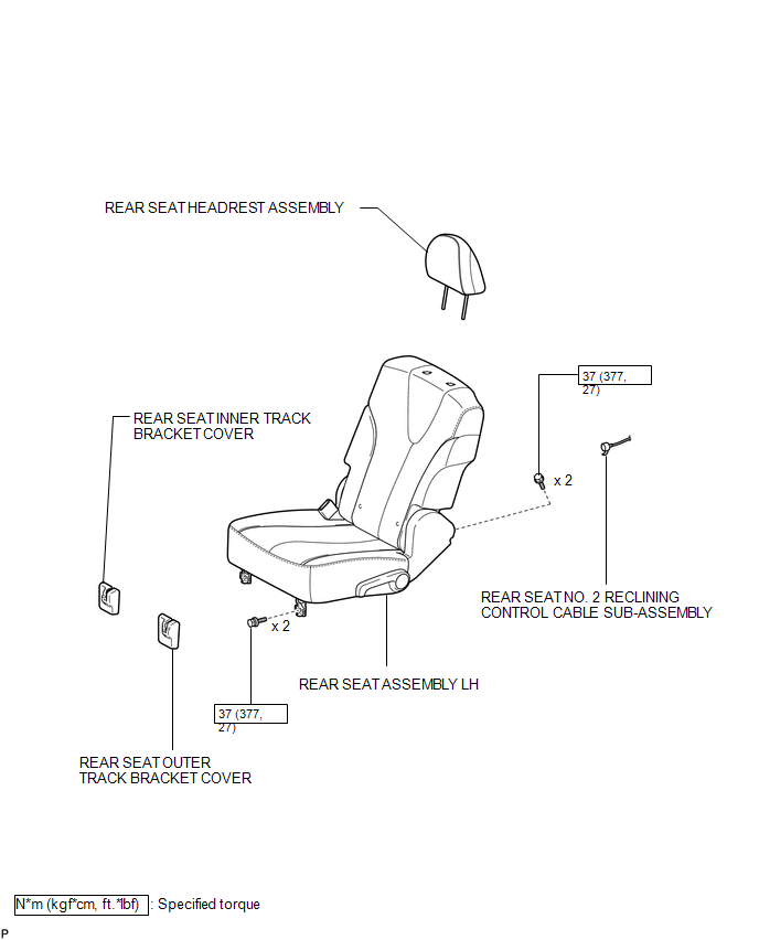
ILLUSTRATION
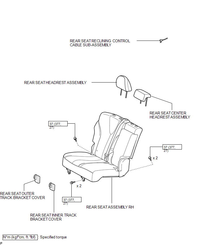
ILLUSTRATION
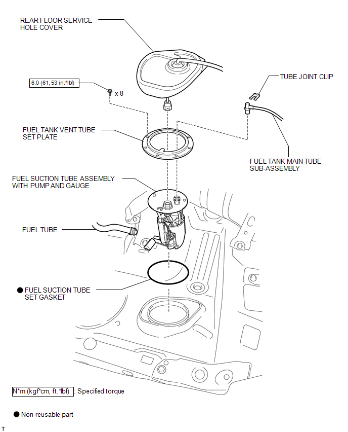
ILLUSTRATION
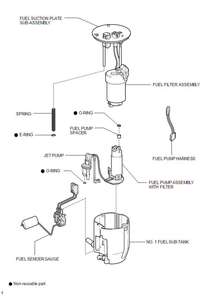
ILLUSTRATION
 Fuel Pump
...
 Removal
REMOVAL
CAUTION / NOTICE / HINT
HINT:
Perform "Inspection After Repair" after replacing the fuel pump assembly (See
page ).
PROCEDURE
1. DISCHARGE FUEL SYSTEM PRESSURE
(a) Discharge ...
Other materials about Toyota Venza:
Portable Player cannot be Connected Manually/Automatically
CAUTION / NOTICE / HINT
HINT:
Some versions of "Bluetooth" compatible audio players may not function properly,
or the functions may be limited using the navigation receiver assembly, even if
the portable audio player itself can play files (See ...
Reassembly
REASSEMBLY
CAUTION / NOTICE / HINT
NOTICE:
Before installation, apply high temperature grease to the parts indicated by
arrows (See page ).
PROCEDURE
1. INSTALL NO. 2 PARKING BRAKE SHOE HOLD DOWN SPRING PIN (for 2WD)
(a) Install the No. 2 p ...
Hill-start assist control
Hill-start assist control helps to prevent the vehicle from rolling backwards
when starting on incline or slippery slope.
To engage hill-start assist control, further depress the brake pedal when the
vehicle is stopped completely.
A buzzer will sound o ...

0.1451