Toyota Venza: Disassembly
DISASSEMBLY
PROCEDURE
1. REMOVE PROPELLER SHAFT
|
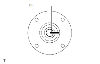
(a) Place matchmarks on both flanges. Text in Illustration
|
|
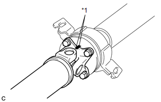
(b) Remove the 4 nuts, 4 bolts and 4 washers.
2. REMOVE INTERMEDIATE SHAFT
|
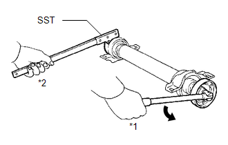
(a) Place matchmarks on the intermediate shaft and rear propeller shaft. NOTICE: Do not place matchmarks with a punch. Text in Illustration
|
|
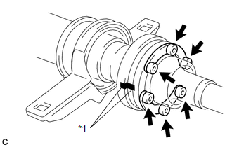
(b) Using a hexagon wrench (6 mm), remove the 6 bolts, 2 washers and intermediate shaft from the rear propeller shaft.
3. REMOVE NO. 1 CENTER SUPPORT BEARING ASSEMBLY
|
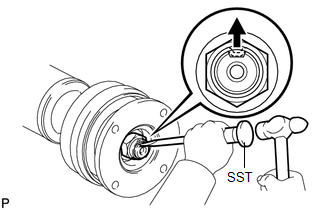
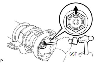
(a) Using SST and a hammer, loosen the staked part of the nut. SST: 09930-00010 |
|
|
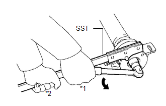
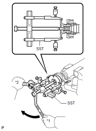
(b) Using SST to hold the universal joint flange, remove the nut and washer SST: 09330-00021 Text in Illustration
|
|
|
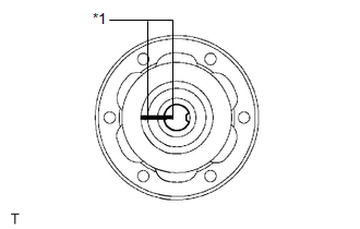
(c) Place matchmarks on the universal joint flange and intermediate shaft. Text in Illustration
|
|
|
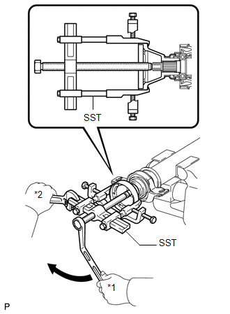
(d) Hold the intermediate shaft in a vise using aluminum plates and remove the universal joint flange using SST. SST: 09950-40011 09951-04020 09952-04010 09953-04030 09954-04010 09955-04061 09957-04010 09958-04011 NOTICE:
|
|
(e) Remove the No. 1 center support bearing assembly and washer.
4. REMOVE NO. 2 CENTER SUPPORT BEARING ASSEMBLY
|
(a) Using SST and a hammer, loosen the staked part of the nut. SST: 09930-00010 |
|
|
(b) Using SST to hold the universal joint flange, remove the nut and washer. SST: 09330-00021 Text in Illustration
|
|
|
(c) Place matchmarks on the universal joint flange and intermediate shaft. Text in Illustration
|
|
|
(d) Hold the intermediate shaft in a vise using aluminum plates and remove the universal joint flange using SST. SST: 09950-40011 09951-04020 09952-04010 09953-04030 09954-04010 09955-04061 09957-04010 09958-04011 NOTICE:
|
|
(e) Remove the No. 2 center support bearing assembly and washer.
 Removal
REMOVAL
PROCEDURE
1. REMOVE TAIL EXHAUST PIPE ASSEMBLY (for 1AR-FE)
2. REMOVE TAIL EXHAUST PIPE ASSEMBLY (for 2GR-FE)
3. REMOVE CENTER EXHAUST PIPE ASSEMBLY (for 1AR-FE)
4. REMOVE CENTER ...
 Inspection
INSPECTION
PROCEDURE
1. INSPECT UNIVERSAL JOINT SPIDER ASSEMBLY
(a) Check the spider bearing axial play by turning the flange while holding
the shaft tightly.
HINT:
If necessar ...
Other materials about Toyota Venza:
Problem Symptoms Table
PROBLEM SYMPTOMS TABLE
HINT:
Use the table below to help determine the cause of problem symptoms.
If multiple suspected areas are listed, the potential causes of the symptoms
are listed in order of probability in the "Suspected Area" ...
Evaporative Emission System Switching Valve Control Circuit High (P2420)
DTC SUMMARY
DTC No.
Monitoring Item
Malfunction Detection Condition
Trouble Area
Detection Timing
Detection Logic
P2420
Vent valve stuck open (vent)
Follo ...
Stereo Component Amplifier Malfunction (B15A3)
DESCRIPTION
This DTC is stored when a malfunction occurs in the stereo component amplifier
assembly.
DTC No.
DTC Detection Condition
Trouble Area
B15A3
When any of the following conditions is met ...

0.1163