Toyota Venza: Certification Ecu
Components
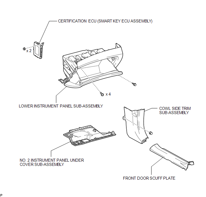
COMPONENTS
ILLUSTRATION
Removal
REMOVAL
PROCEDURE
1. DISCONNECT CABLE FROM NEGATIVE BATTERY TERMINAL
CAUTION:
Wait at least 90 seconds after disconnecting the cable from the negative (-) battery terminal to disable the SRS system.
NOTICE:
When disconnecting the cable, some systems need to be initialized after the cable
is reconnected (See page .gif) ).
).
2. REMOVE FRONT DOOR SCUFF PLATE
HINT:
Use the same procedure for the RH side and LH side (See page
).
3. REMOVE COWL SIDE TRIM SUB-ASSEMBLY
HINT:
Use the same procedure for the RH side and LH side (See page
).
4. REMOVE NO. 2 INSTRUMENT PANEL UNDER COVER SUB-ASSEMBLY
5. REMOVE LOWER INSTRUMENT PANEL SUB-ASSEMBLY
6. REMOVE CERTIFICATION ECU (SMART KEY ECU ASSEMBLY)
|
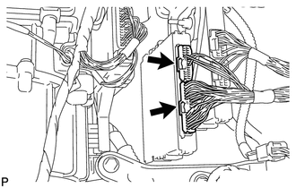
(a) Disconnect each connector. |
|
|
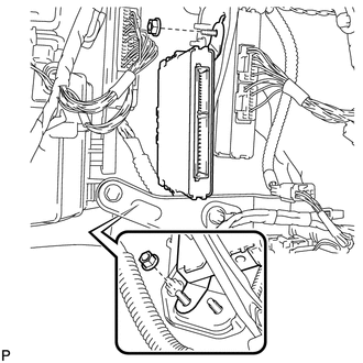
(b) Remove the 2 nuts and the certification ECU (smart key ECU assembly). |
|
Installation
INSTALLATION
PROCEDURE
1. INSTALL CERTIFICATION ECU (SMART KEY ECU ASSEMBLY)
|
(a) Install the certification ECU (smart key ECU assembly) with the 2 nuts. |
|
.png)
|
(b) Connect each connector. |
|
.png)
2. INSTALL LOWER INSTRUMENT PANEL SUB-ASSEMBLY
.gif)
3. INSTALL NO. 2 INSTRUMENT PANEL UNDER COVER SUB-ASSEMBLY
4. INSTALL COWL SIDE TRIM SUB-ASSEMBLY
HINT:
Use the same procedure for the RH side and LH side (See page
).
5. INSTALL FRONT DOOR SCUFF PLATE
HINT:
Use the same procedure for the RH side and LH side (See page
).
6. CONNECT CABLE TO NEGATIVE BATTERY TERMINAL
NOTICE:
When disconnecting the cable, some systems need to be initialized after the cable
is reconnected (See page ).
7. REGISTER KEY
NOTICE:
When replacing the certification ECU (smart key ECU assembly), perform initialization
(See page ).
8. REGISTER ECU COMMUNICATION ID
NOTICE:
When replacing the certification ECU (smart key ECU assembly), perform initialization
(See page ).

 Electrical Key Oscillator(for Center Floor)
Components
COMPONENTS
ILLUSTRATION
Installation
INSTALLATION
PROCEDURE
1. INSTALL ELECTRICAL KEY OSCILLATOR
(a) Engage the clamp and install the electrical key oscillator.
N ...
Other materials about Toyota Venza:
Display does not Dim when Light Control Switch is Turned ON
PROCEDURE
1.
CHECK IMAGE QUALITY SETTING
(a) Turn the light control switch to the tail or head position.
(b) Check that the daytime screen setting on the display adjustment screen is
set to on.
Result
...
Interior Light Power Source Circuit
DESCRIPTION
The main body ECU (driver side junction block assembly) controls operation of
the DOME CUT relay in order to supply power to the interior lights.
WIRING DIAGRAM
CAUTION / NOTICE / HINT
NOTICE:
Inspect the fuses for circuits related to this ...
Front passenger occupant classification system
Your vehicle is equipped with a front passenger occupant classification system.
This system detects the conditions of the front passenger seat and activates or
deactivates the devices for front passenger.
1. SRS warning light
2. Front passenger’s sea ...

0.1157