Toyota Venza: When the TRAC/VSC system are operating
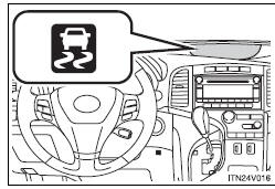
The slip indicator light will flash while the TRAC/VSC systems are operating.
 Driving assist systems
To help enhance driving safety and performance, the following systems operate
automatically in response to various driving situations.
Be aware, however, that these systems are supplementary and sh ...
 Disabling the TRAC system
If the vehicle gets stuck in mud, dirt or snow, the TRAC system may reduce power
from the engine to the wheels. Pressing
to turn the system off may make it
easier for you to rock the vehicle in ...
Other materials about Toyota Venza:
Installation
INSTALLATION
PROCEDURE
1. INSTALL COOLER CONDENSER ASSEMBLY
(a) Install the cooler condenser assembly with the 4 bolts.
Torque:
6.0 N·m {61 kgf·cm, 53 in·lbf}
HINT:
If the condenser is replaced with a new one, add compressor oil t ...
Data List / Active Test
DATA LIST / ACTIVE TEST
1. READ DATA LIST
HINT:
Using the Techstream to read the Data List allows the values or states of switches,
sensors, actuators and other items to be read without removing any parts. This non-intrusive
inspection can be very usefu ...
Brake Line
Precaution
PRECAUTION
1. TROUBLESHOOTING PRECAUTION
NOTICE:
Since the brake lines are critical safety related parts, be sure to
disassemble and inspect the components if a brake fluid leak is found. If
any abnormality is found, replace th ...

0.1554