Toyota Venza: Open in Outside Luggage Compartment Electrical Key Antenna Circuit (B27A8)
DESCRIPTION
The certification ECU (smart key ECU assembly) generates a request signal and sends it to the outside electrical key oscillator (for rear side). To detect the key near the driver door, the outside electrical key oscillator (for rear side) creates a detection area towards the area approximately 1.0 m (3.28 ft.) from the back door.
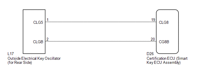
DTC B27A8 is detected by the certification ECU (smart key ECU assembly) when an open circuit occurs between the certification ECU (smart key ECU assembly) and outside electrical key oscillator (for rear side) terminals (between CLG8 and CLG5, or CG8B and CLGB).
|
DTC No. |
DTC Detection Condition |
Trouble Area |
|---|---|---|
|
B27A8 |
Open circuit detected between the certification ECU (smart key ECU assembly and outside electrical key oscillator (for rear side) terminals (between CLG8 and CLG5, or CG8B and CLGB). |
|
WIRING DIAGRAM
CAUTION / NOTICE / HINT
NOTICE:
The smart key system (for entry function) uses a multiplex communication system
(LIN communication system) and CAN communication system. Inspect the communication
function by following How to Proceed with Troubleshooting (See page
.gif) ). Troubleshoot the smart key system (for entry
). Troubleshoot the smart key system (for entry
function) after confirming that the communication system is functioning properly.
PROCEDURE
|
1. |
CHECK CONNECTOR CONNECTION CONDITION |
(a) Turn the engine switch off.
(b) Check that the connectors are properly connected to the certification ECU (smart key ECU assembly) and the outside electrical key oscillator (for rear side).
OK:
Connectors are properly connected.
| NG | .gif) |
CONNECT CONNECTORS PROPERLY |
|
.gif)
|
2. |
CHECK HARNESS AND CONNECTOR (CERTIFICATION ECU - OUTSIDE ELECTRICAL KEY OSCILLATOR) |
(a) Disconnect the certification ECU (smart key ECU assembly) connector.
|
(b) Disconnect the outside electrical key oscillator (for rear side) connector. |
|
(c) Measure the resistance according to the value(s) in the table below.
Standard Resistance:
|
Tester Connection |
Condition |
Specified Condition |
|---|---|---|
|
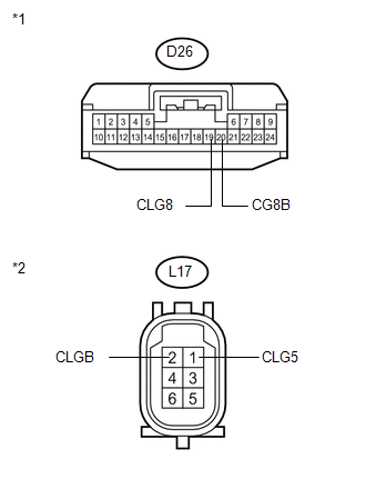
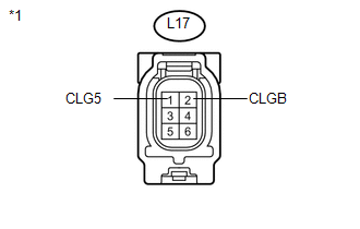
D26-19 (CLG8) - L17-1 (CLG5) |
Always |
Below 1 Ω |
|
D26-20 (CG8B) - L17-2 (CLGB) |
Always |
Below 1 Ω |
|
D26-19 (CLG8) - Body ground |
Always |
10 kΩ or higher |
|
D26-20 (CG8B) - Body ground |
Always |
10 kΩ or higher |
|
L17-1 (CLG5) - Body ground |
Always |
10 kΩ or higher |
|
L17-2 (CLGB) - Body ground |
Always |
10 kΩ or higher |
|
*1 |
Front view of wire harness connector (to Certification ECU (Smart Key ECU Assembly)) |
|
*2 |
Front view of wire harness connector (to Outside Electrical Key Oscillator (for Rear Side)) |
| NG | |
REPAIR OR REPLACE HARNESS OR CONNECTOR |
|
|
3. |
INSPECT OUTSIDE ELECTRICAL KEY OSCILLATOR |
|
(a) Measure the resistance according to the value(s) in the table below. Standard Resistance:
|
|
| NG | |
REPLACE OUTSIDE ELECTRICAL KEY OSCILLATOR |
|
|
4. |
REPLACE CERTIFICATION ECU (SMART KEY ECU ASSEMBLY) |
(a) Replace the certification ECU (smart key ECU assembly) (See page
).
|
|
5. |
CHECK DTC OUTPUT |
(a) Clear the DTCs (See page ).
(b) Recheck for DTCs.
OK:
DTC B27A8 is not output.
| OK | |
END (CERTIFICATION ECU (SMART KEY ECU ASSEMBLY) WAS DEFECTIVE) |
| NG | |
REPLACE OUTSIDE ELECTRICAL KEY OSCILLATOR |
 Diagnostic Trouble Code Chart
DIAGNOSTIC TROUBLE CODE CHART
HINT:
If a trouble code is stored during the DTC check, inspect the trouble areas listed
for that code. For details of the code, refer to the "See page" bel ...
 Open in Rear Floor Electrical Key Oscillator Circuit (B27A6)
DESCRIPTION
The certification ECU (smart key ECU assembly) generates a request signal and
sends it to the indoor electrical key oscillator (for center floor). To detect the
key inside the cabin, ...
Other materials about Toyota Venza:
Power Back Door Warning Buzzer
Components
COMPONENTS
ILLUSTRATION
Inspection
INSPECTION
PROCEDURE
1. INSPECT POWER BACK DOOR WARNING BUZZER
(a) Measure the resistance according to the value(s) in the table below.
HINT:
If battery voltage is applied directly to ...
Problem Symptoms Table
PROBLEM SYMPTOMS TABLE
HINT:
Use the table below to help determine the cause of problem symptoms.
If multiple suspected areas are listed, the potential causes of the symptoms
are listed in order of probability in the "Suspected Area" ...
Data Signal Circuit between Radio Receiver and Stereo Jack Adapter
DESCRIPTION
The No. 1 stereo jack adapter assembly sends the sound data signal or image data
signal from a USB device to the radio and display receiver assembly via this circuit.
WIRING DIAGRAM
PROCEDURE
1.
CHECK HARNESS AND CONN ...

0.1243